
NEUTRAL SWITCH / EGR VALVE POSITION SENSOR
F2-158prose procedureNeutral switch applies to A/T transaxle.
CONTROL SYSTEM
NEUTRAL SWITCH
Inspection
Neutral Switch Inspection
- 1Disconnect the neutral switch connector shown in the figure.
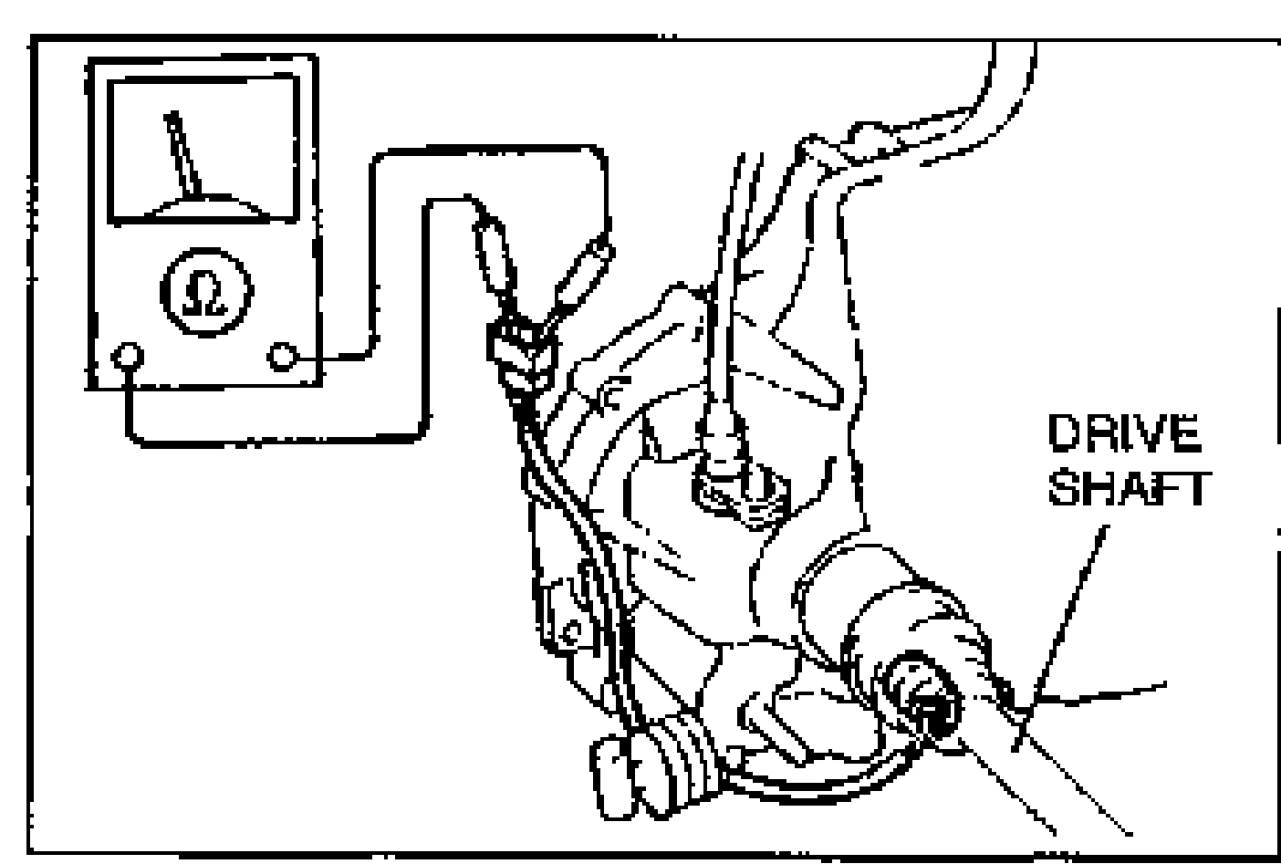
- 2Connect an ohmmeter to the switch.
- 3Check continuity of the switch.
- 4If not as specified, replace the neutral switch.
Neutral Switch Continuity
Neutral
ContinuityYes
Other ranges
ContinuityNo
Replacement
Neutral Switch Replacement
- 1Disconnect the neutral switch connector.
- 2Remove the bracket.
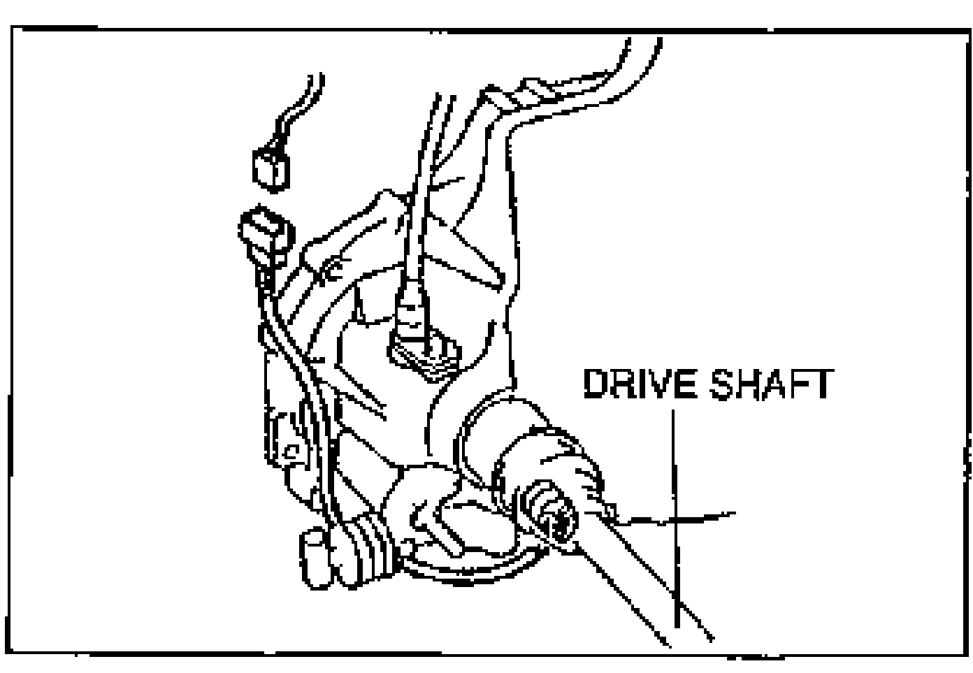
- 3Remove the neutral switch.
- 4Install in the reverse order of removal.
| Specification | Value |
|---|---|
| neutral switch | 20 - 29N·m |
neutral switch
20 - 29N·m
EGR VALVE POSITION SENSOR
Inspection of Output Voltage
EGR Valve Position Sensor Inspection of Output Voltage
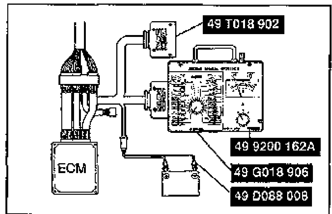
- 1Disconnect the ECM connector.
- 2Connect the SSTs (Engine Signal Monitor and Adapter) to the ECM as shown and connect a vacuum pump.
- 3Turn the ignition switch to ON.
- 4Measure voltage at the terminals as shown in the table.
- 5If not correct at terminals A and B, check the wiring harness and terminals 2I and 3D of the ECM.
- 6If not correct at terminal C, measure the sensor resistance, then the wiring harness and terminal 2F of the ECM.
EGR Valve Position Sensor Output Voltage
C
ECM2I
Vacuum 0 mmHg {0 inHg}4.5-5.5V
Vacuum 150 mmHg {5.9 inHg}4.5-5.5V
B
ECM3D
Vacuum 0 mmHg {0 inHg}Below 1.5V
Vacuum 150 mmHg {5.9 inHg}Below 1.5V
A
ECM2J
Vacuum 0 mmHg {0 inHg}Approx. 0.7V
Vacuum 150 mmHg {5.9 inHg}Approx. 4.7V
Inspection of Resistance
EGR Valve Position Sensor Inspection of Resistance
- 1Disconnect the EGR valve position sensor connector, and connect an ohmmeter.
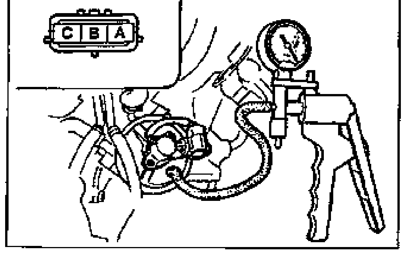
- 2Disconnect the vacuum hose from the EGR valve, and connect a vacuum pump.
- 3Measure the resistance between terminals as shown in the table.
EGR Valve Position Sensor Resistance
C-B
ECM2I-3D
Vacuum 0 mmHg {0 inHg}4.6 KΩ
Vacuum 150 mmHg {5.9 inHg}4.6 KΩ
A-B
ECM2J-3D
Vacuum 0 mmHg {0 inHg}Approx. 2.3 KΩ
Vacuum 150 mmHg {5.9 inHg}Approx. 5.8 KΩ
A-C
ECM2J-2I
Vacuum 0 mmHg {0 inHg}Approx. 5.3 KΩ
Vacuum 150 mmHg {5.9 inHg}Approx. 1.2 KΩ