
On Board Diagnostic System — After-Repair Procedure / Switch Monitor Function
F2-92prose procedureSwitch list distinguishes MTX (manual) clutch/neutral switches vs ATX (automatic) transaxle range switch; DRL row applies to Canada-spec vehicles; A/C switch row noted as if equipped.
After-Repair Procedure
- 1Cancel the memory of diagnostic trouble code number by disconnecting the negative battery cable and depressing the brake pedal for at least 20 seconds. Reconnect the negative battery cable.
- 2Connect the SST to the data link connector.
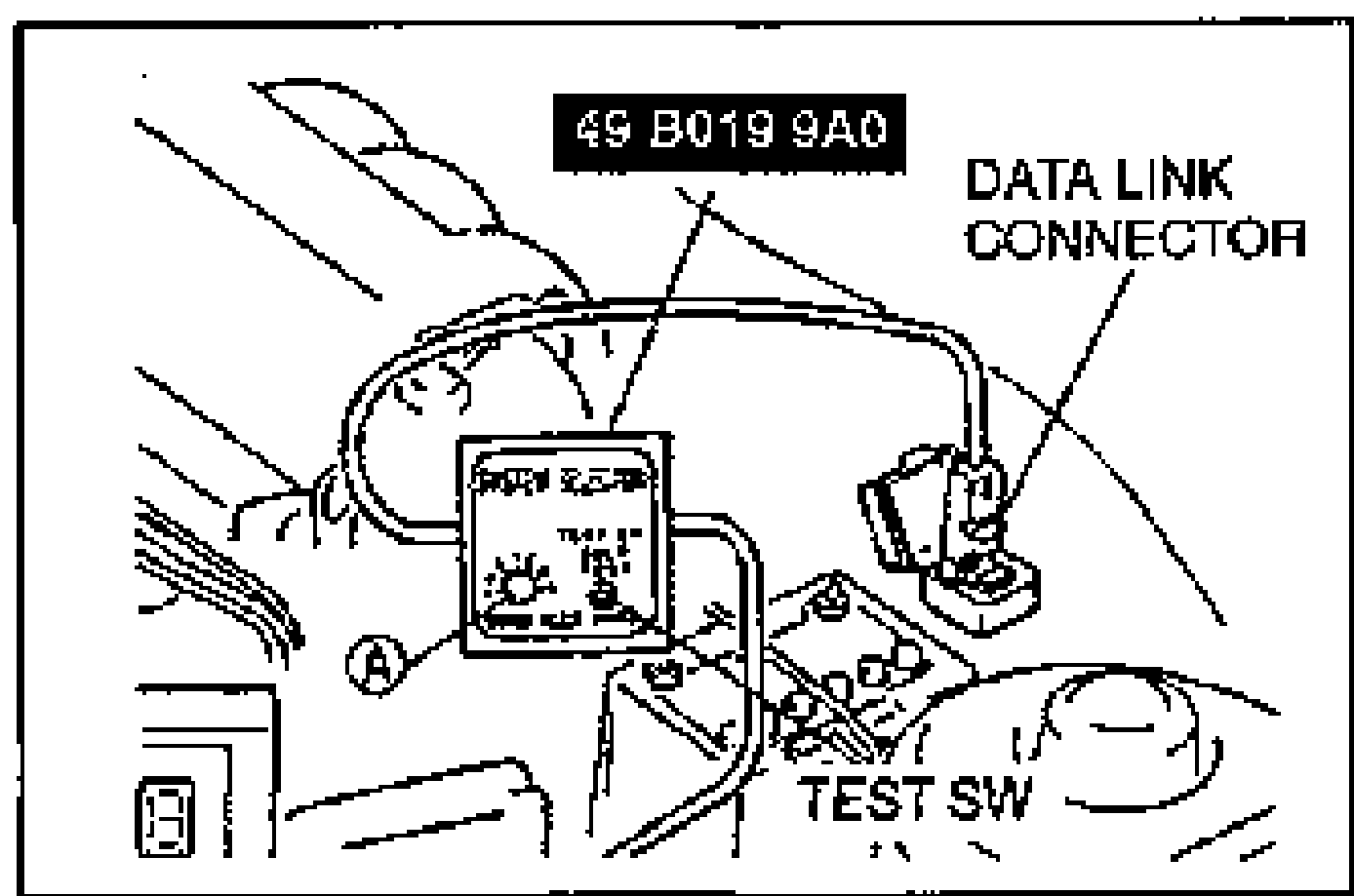
- 3Verify that no diagnostic trouble code numbers are displayed.
SWITCH MONITOR FUNCTION
Individual switches can be inspected by using the SST (Self-Diagnosis Checker).
Preparation
Ground the data link connector terminal TEN and turn the ignition switch to ON (engine off). If any switch remains activated, the monitor light will be illuminated.
Switch Monitor — Self-Diagnosis Checker (Monitor light)
Clutch switch (MTX)
Light ONClutch pedal released
Light OFFClutch pedal depressed
RemarksIn gear
Neutral switch (MTX)
Light ONIn gear
Light OFFNeutral
RemarksClutch pedal released
Transaxle range switch (ATX)
Light ONON
Light OFFOFF
Remarks—
Closed throttle position switch
Light ONAccelerator pedal depressed
Light OFFAccelerator pedal released
Remarks—
Brake switch
Light ONBrake pedal depressed
Light OFFBrake pedal released
Remarks—
Headlight switch
Light ONON
Light OFFOFF
RemarksHeadlight ON
DRL (CANADA)
Light ONON
Light OFFOFF
RemarksON: parking lever released
Fan switch
Light ONON
Light OFFOFF
RemarksAt 2nd or higher position
A/C switch (if equipped)
Light ONON
Light OFFOFF
RemarksBlower switch at 1st position
Rear window defroster switch
Light ONON
Light OFFOFF
Remarks—
Inspection Procedure
- 1Connect the SST (System Selector) to the data link connector.
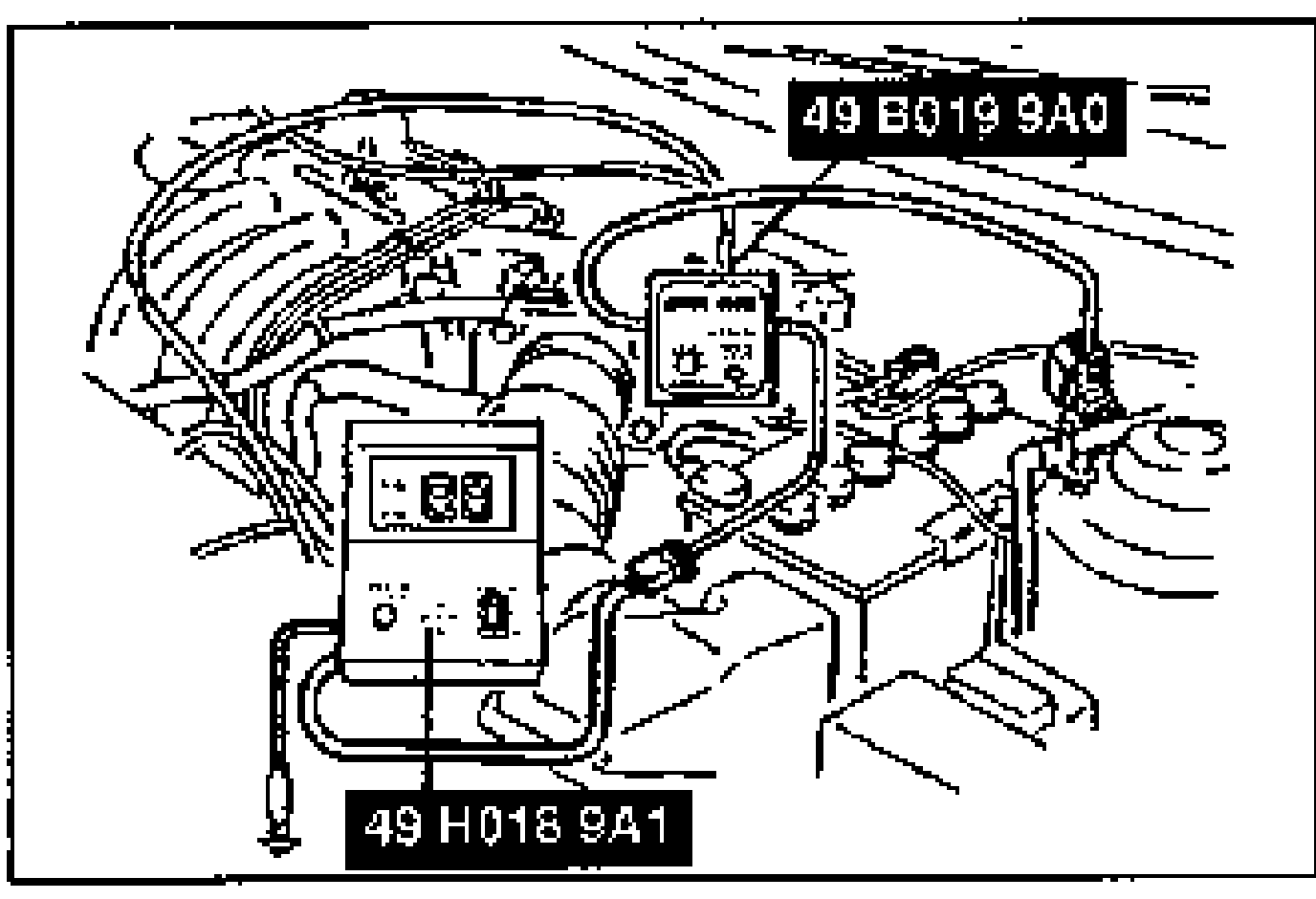
- 2Set switch A to position 1.
- 3Set TEST SW to SELF TEST.
- 4Connect the SST (Self-Diagnosis Checker) to the System Selector and a ground.
- 5Set the select switch of the Self-Diagnosis Checker to position A.
- 6Turn the ignition switch to ON.
- 7Pull the parking brake lever.
- 8Verify that the monitor light illuminates when each switch is made to function as described.