
EXHAUST GAS RECIRCULATION (EGR) CONTROL SYSTEM
F2-126prose procedureSystem Inspection
- 1Connect the SSTs (Engine Signal Monitor and Adaptor Harness) to the ECM as shown (Refer to page F2-141.)
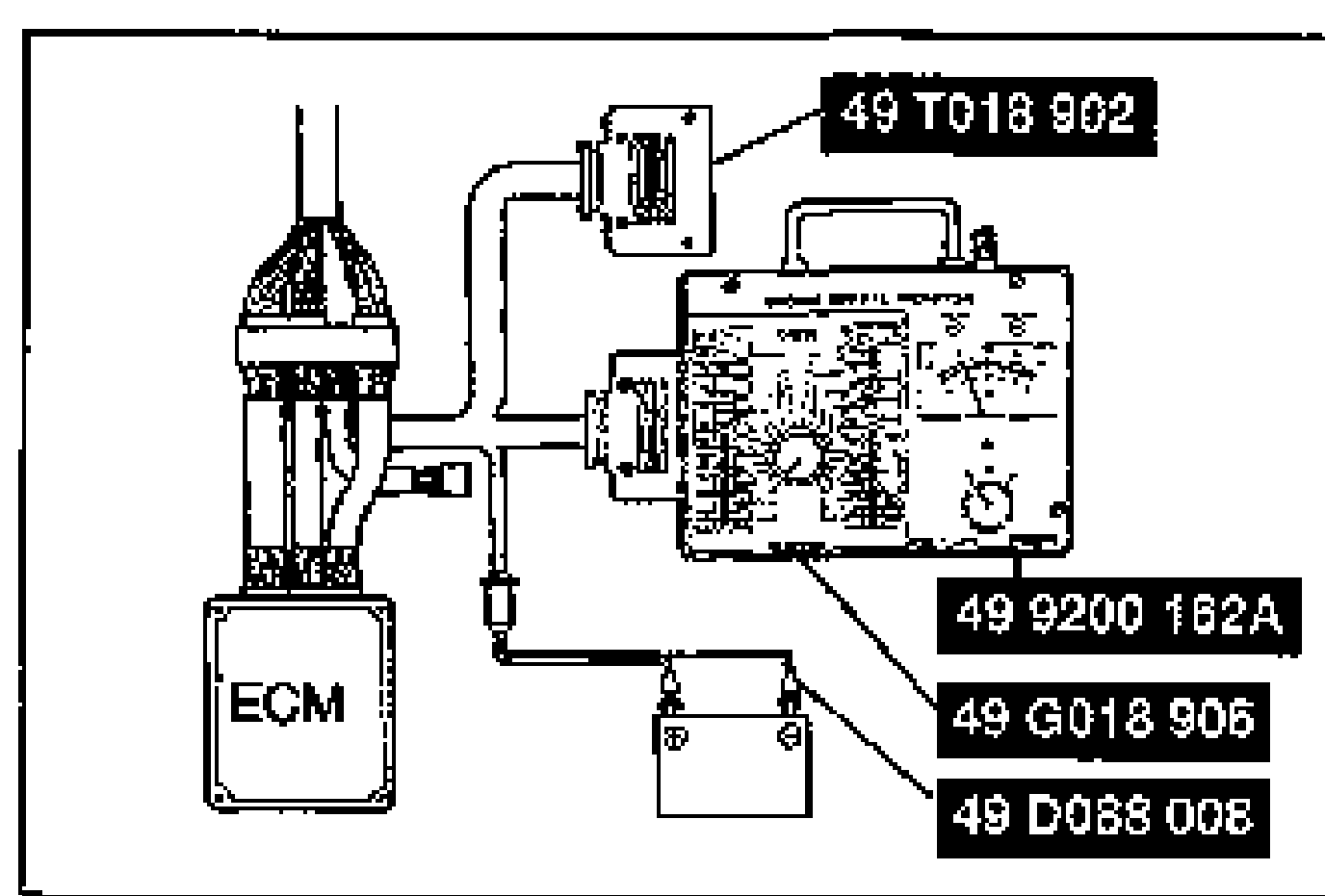
- 2Start the engine.
- 3Accelerate the engine and verify that ECM terminal 3O and 3P voltages are battery positive voltage while the engine is still cold.
- 4Warm up the engine to normal operating temperature.
- 5Drive the vehicle and verify that Engine Signal Monitor green and red lights flash at ECM terminals 3O and 3P.
- 6Disconnect the EGR solenoid valve (Vacuum) connector.
- 7Apply battery positive voltage and a ground to the solenoid valve as shown.
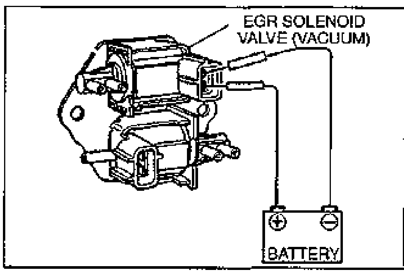
- 8Verify that the engine runs roughly or stalls at idle.
EGR SOLENOID VALVE (VACUUM)
Inspection
- 1Disconnect the vacuum hoses.
- 2Blow through the vacuum hose and verify that air does not flow.
- 3Disconnect the solenoid valve connector.
- 4Apply battery positive voltage and a ground to the solenoid valve as shown.
- 5Below through the vacuum hose and verify that air flows.
- 6If not as specified, replace the solenoid valves.
EGR SOLENOID VALVE (VENT)
Inspection
- 1Disconnect the vacuum hoses.
- 2Blow through the vacuum hose and verify that air flows.
- 3Disconnect the solenoid valve connector.
- 4Apply battery positive voltage and a ground to the solenoid valve as shown.
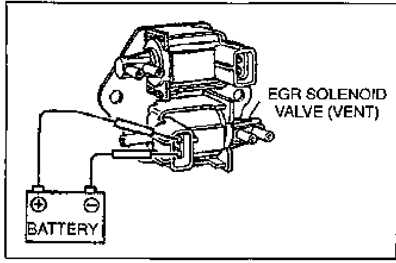
- 5Blow through the vacuum hose and verify that air does not flow.
- 6If not as specified, replace the solenoid valves.
EGR VALVE
Inspection
- 1Start the engine and run it at idle.
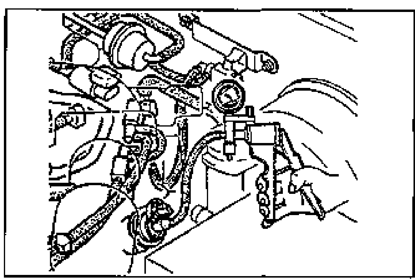
- 2Connect a vacuum pump as shown and apply vacuum.
- 3Verify that the engine runs roughly or stalls at more than the specified vacuum.Specification: 40-60 mmHg {1.6-2.4 inHg}
- 4If not as specified, replace the EGR valve.
| Specification | Value |
|---|---|
| EGR valve vacuumengine runs roughly or stalls | 40-60mmHg {1.6-2.4 inHg} |
EGR valve vacuumengine runs roughly or stalls
40-60mmHg {1.6-2.4 inHg}