
HEATED OXYGEN SENSOR (Right bank, Left bank)
F2-154prose procedureRight bank / left bank heated oxygen sensors selected via brake pedal state during monitoring (V6 K8 engine).
CONTROL SYSTEM
HEATED OXYGEN SENSOR (Right bank, Left bank)
Inspection
Heated Oxygen Sensor Inspection
- 1Warm up the engine to normal operating temperature and run it at idle.
- 2Disconnect the heated oxygen sensor connector.
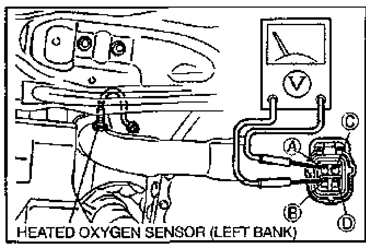
- 3Connect a voltmeter between the heated oxygen sensor and a ground.
- 4Run the engine at 4,500 rpm until voltmeter indicates approx. 0.7V.
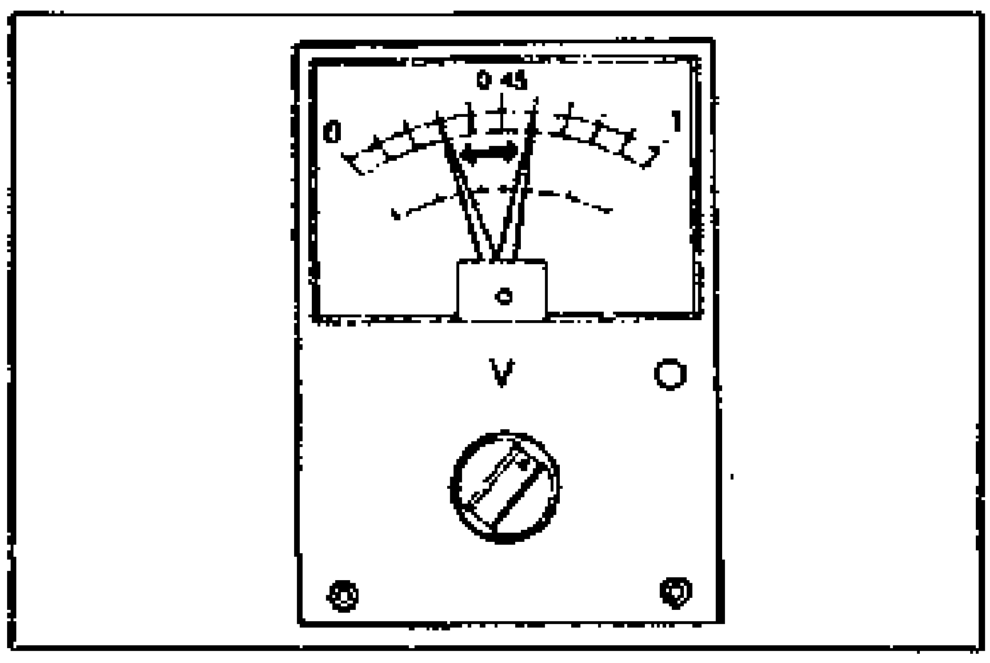
- 5Measure the voltage while increasing and decreasing the engine speed suddenly several times.
Specification
Voltage Specification
While deceleration
Voltage (V)Below 0.4
While acceleration
Voltage (V)Above 0.5
Heated Oxygen Sensor Inspection (continued)
- 6Connect the SSTs (System Selector and Self-Diagnosis Checker) to the data link connector as shown.
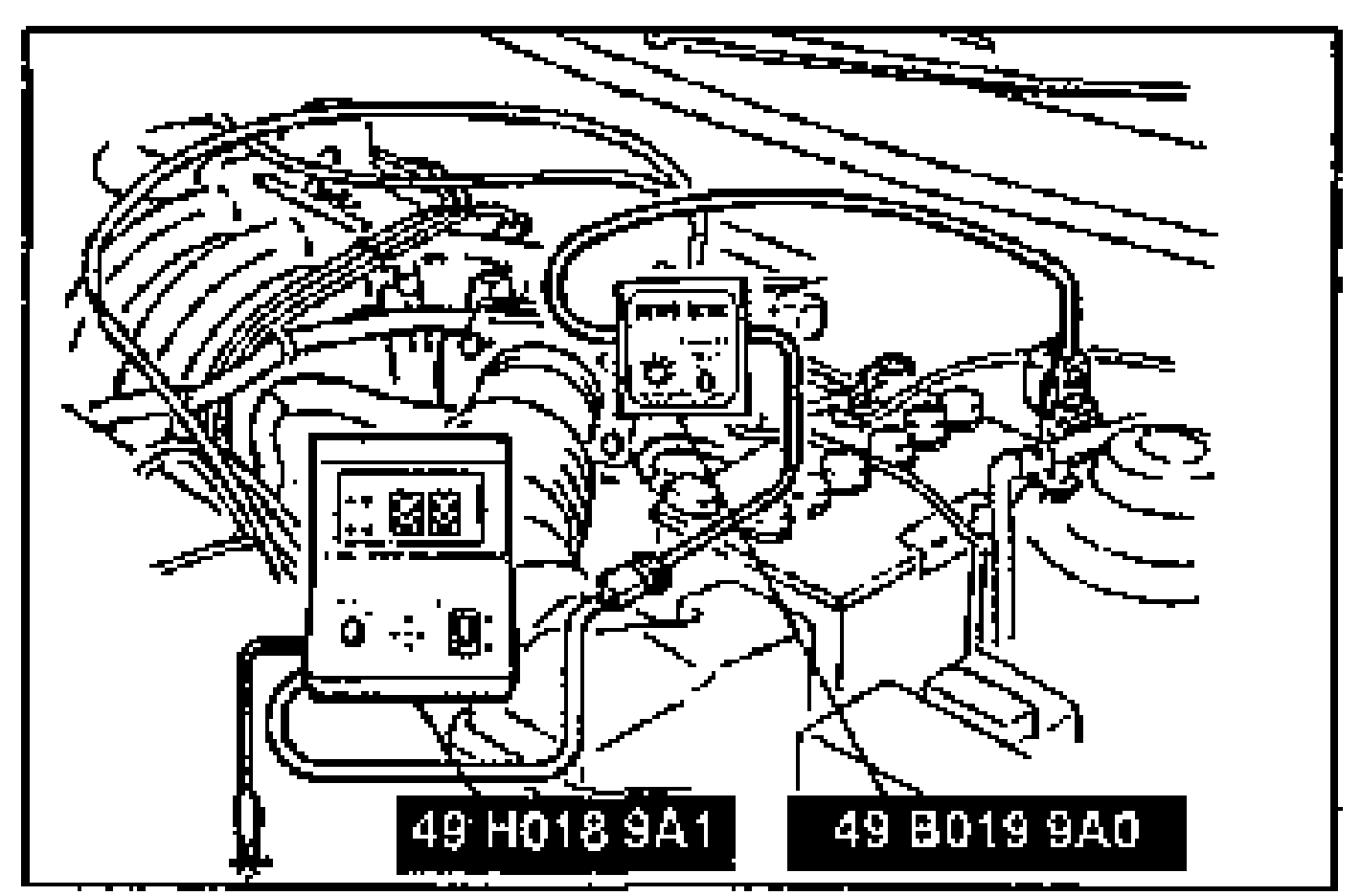
- 7Set switch A to position 1.
- 8Set TEST SW to O2 MONITOR.
- 9Increase the engine speed to 2,000-3,000 rpm, and verify that the monitor light flashes for 10 sec. If not as specified, replace the heated oxygen sensor.With the brake pedal depressed, the monitor lamp shows operation of the right heated oxygen sensor.With the brake pedal released, the monitor lamp shows operation of the left heated oxygen sensor.
NOTE
With the brake pedal depressed, the monitor lamp shows operation of the right heated oxygen sensor. With the brake pedal released, the monitor lamp shows operation of the left heated oxygen sensor.
Heater
Heated Oxygen Sensor Heater Inspection
- 1Measure resistance between terminals C and D of the heater connector.
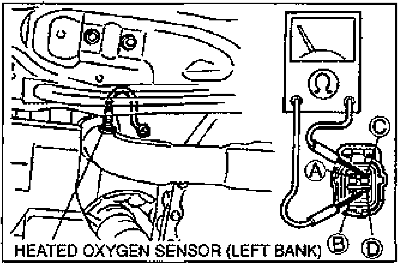
- 2Replace the heater if not as specified.
| Specification | Value |
|---|---|
| Resistance20°C {68°F} | Approx. 13Ω |
Resistance20°C {68°F}
Approx. 13Ω
Replacement
Heated Oxygen Sensor Replacement
- 1Disconnect the heated oxygen sensor connector.
- 2Remove the heated oxygen sensor.
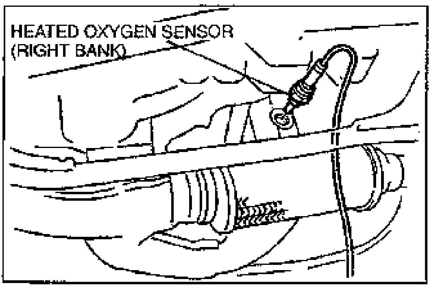
- 3Install in the reverse order of removal.
| Specification | Value |
|---|---|
| heated oxygen sensor | 30 - 49N·m |
heated oxygen sensor
30 - 49N·m