
CRANKSHAFT POSITION SENSOR / CAMSHAFT POSITION SENSOR (IN DISTRIBUTOR)
F2-153prose procedureCONTROL SYSTEM
CRANKSHAFT POSITION SENSOR
Inspection
Crankshaft Position Sensor Inspection
- 1Disconnect the crankshaft position sensor connector.
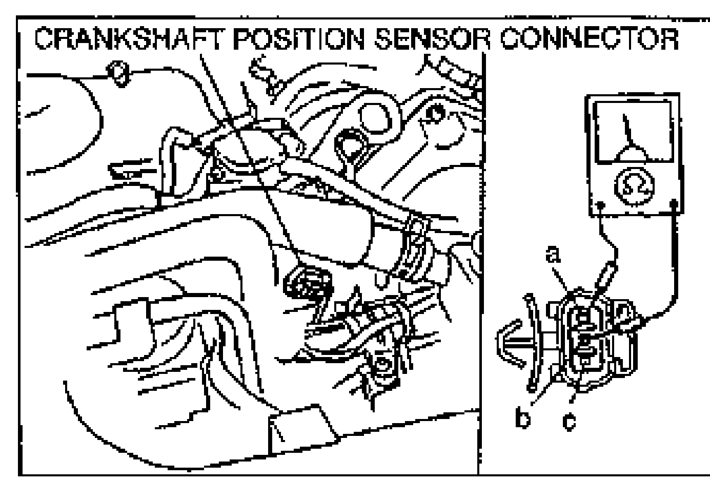
- 2Measure the resistance between terminals A and B.
- 3Replace the crankshaft position sensor if not as specified.
| Specification | Value |
|---|---|
| Resistance20°C {68°F} | 520-580Ω |
Resistance20°C {68°F}
520-580Ω
Removal / Installation
Crankshaft Position Sensor Removal / Installation
- 1Disconnect the negative battery cable.
- 2Remove the idler pulley bracket.
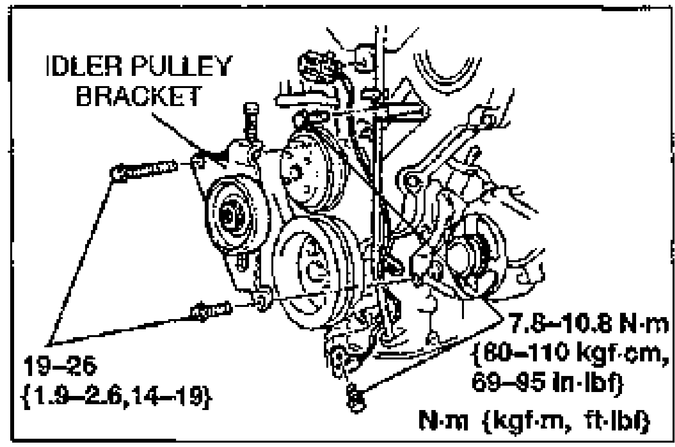
- 3Remove the dipstick pipe.
- 4Remove the crankshaft position sensor.
- 5Install in the reverse order of removal.
- 6Adjust the drive belt deflection. (Refer to section B2.)
CAMSHAFT POSITION SENSOR (IN DISTRIBUTOR)
Inspection
Camshaft Position Sensor (In Distributor) Inspection
- 1Remove the distributor. (Refer to section G.)
- 2Verify that the distributor connector (3-pin) is disconnected.
- 3Connect the distributor connector (6-pin) as shown in the figure.
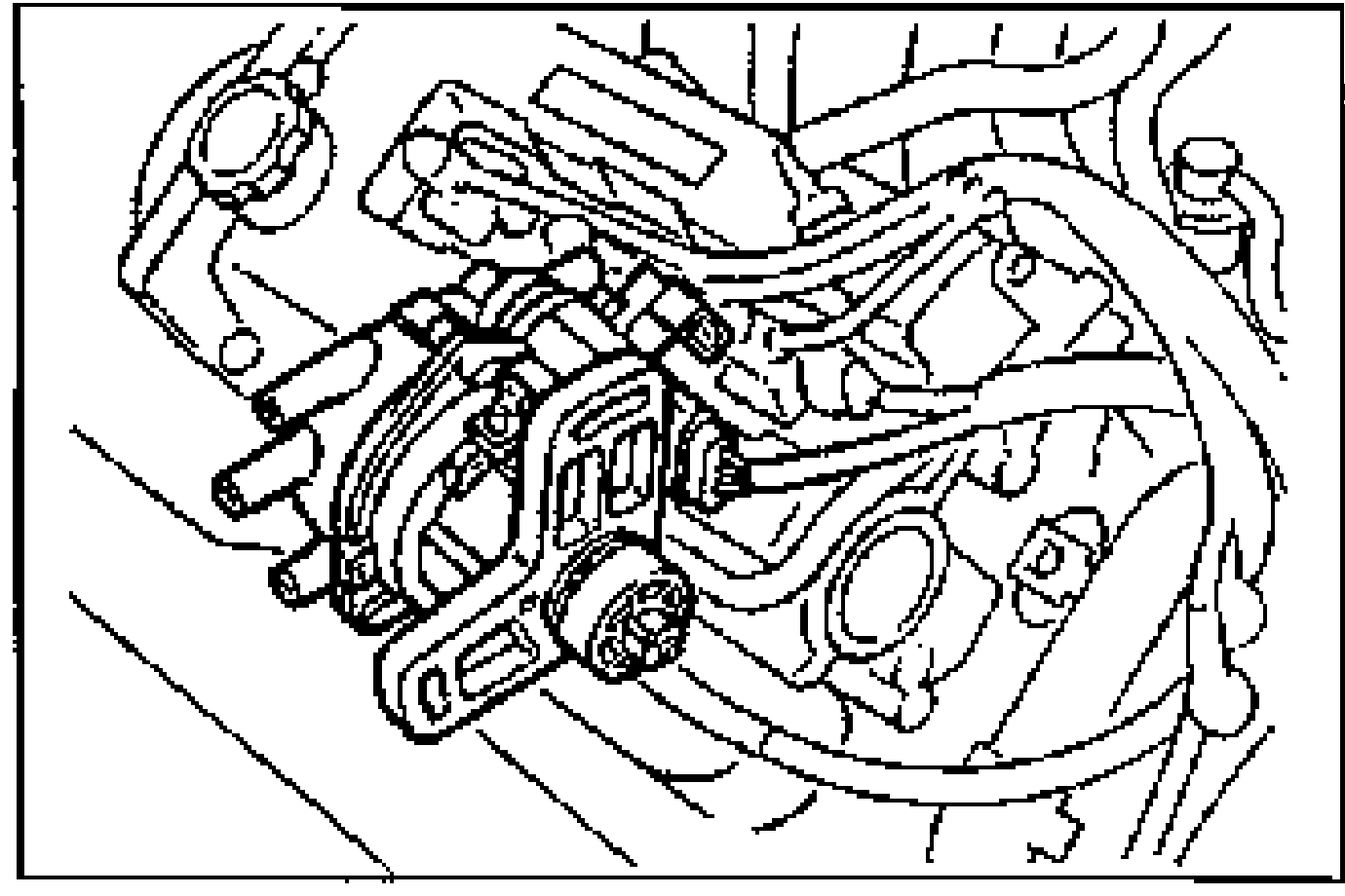
- 4Disconnect the fuel injector connector.
- 5Turn the ignition switch ON.
- 6Connect the SSTs (Engine Signal Monitor and Adapter Harness) to the ECM.
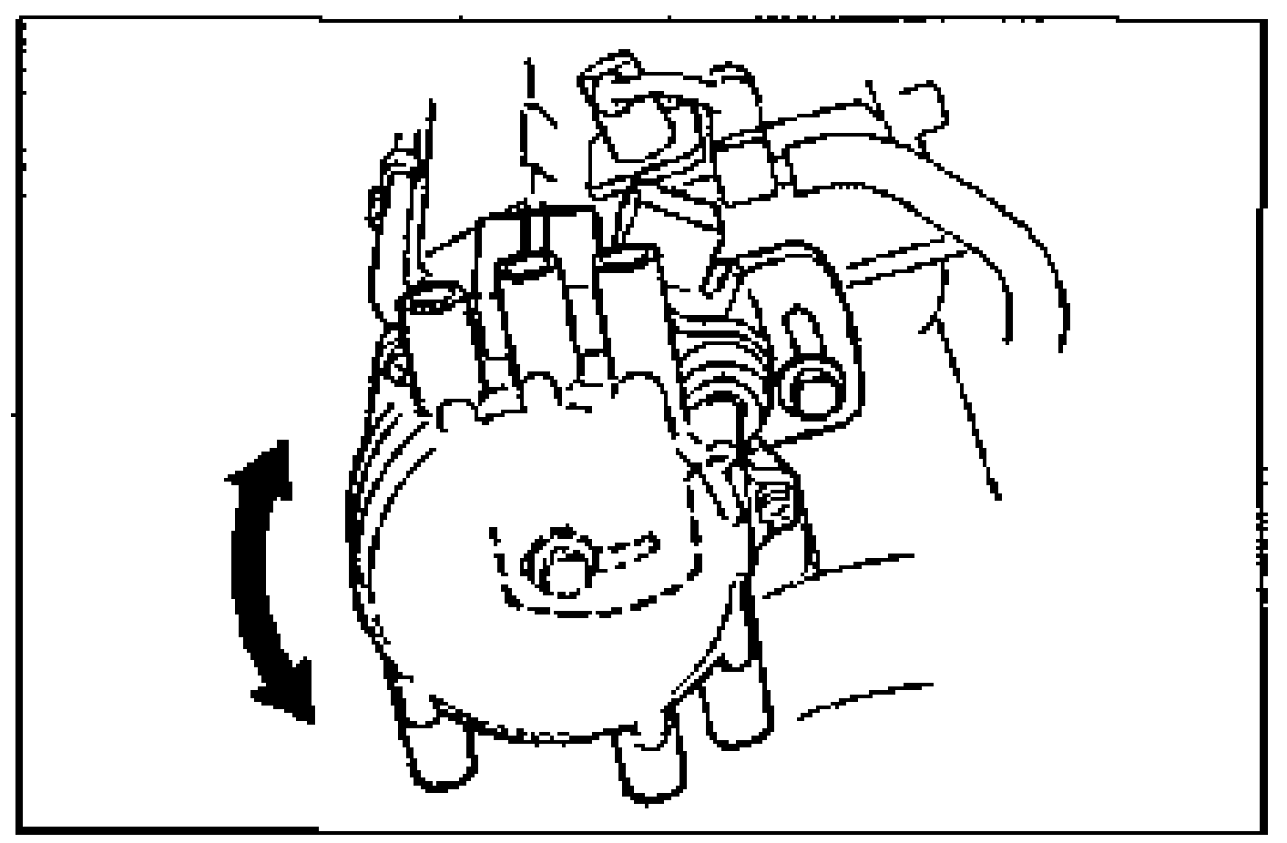
- 7Rotate the distributor drive by hand and measure the output voltage.
Specification
Output Voltage Specification
3E (SGT signal)
VoltageApprox. 5V (6 pulses)
3G (SGC signal)
VoltageApprox. 5V (1 pulse)
Camshaft Position Sensor Inspection (continued)
- 8After the inspection, install the distributor. (Refer to section G.)
- 9Start the engine and adjust the ignition timing. (Refer to page F2-70.)
- 10Tighten the distributor lock bolts to the specified torque.
| Specification | Value |
|---|---|
| Ignition timing | BTDC 9-11°{10 ± 1°} |
| distributor lock bolts | 19 - 25N·m |
Ignition timing
BTDC 9-11°{10 ± 1°}
distributor lock bolts
19 - 25N·m