
DASHBOARD AND CONSOLE — Component legend and Removal notes
S-62prose procedureAir bag-equipped vehicle; driver- and passenger-side air bag module R/I covered in the 1995 Body Electrical Troubleshooting Manual.
Component legend (Dashboard and Console)
1
ComponentSide panel
Removal / Installation referenceRemoval note ... below
2
ComponentHood release lever
Removal / Installation referenceRemoval note ... below
3
ComponentLower panel
Removal / Installation referenceRemoval note ... below
4
ComponentRear console
Removal / Installation referenceRemoval note ... page S-63
5
ComponentAshtray
Removal / Installation reference—
6
ComponentFront console panel
Removal / Installation referenceRemoval note ... page S-63
7
ComponentFront console
Removal / Installation referenceRemoval / note ... page S-63
8
ComponentGlove compartment
Removal / Installation referenceRemoval note ... page S-63
9
ComponentGlove compartment cover
Removal / Installation reference—
10
ComponentPassenger-side air bag module
Removal / Installation referenceRemoval / Installation ... 1995 Body Electrical Troubleshooting Manual, section S
11
ComponentDriver-side air bag module
Removal / Installation referenceRemoval / Installation ... 1995 Body Electrical Troubleshooting Manual, section S
12
ComponentSteering wheel
Removal / Installation referenceRemoval / Installation ... section N
13
ComponentColumn cover
Removal / Installation reference—
14
ComponentCombination switch
Removal / Installation referenceRemoval / Installation ... 1995 Body Electrical Troubleshooting Manual, section Z4
15
ComponentMeter hood
Removal / Installation referenceRemoval note ... page S-64
16
ComponentInstrument cluster
Removal / Installation referenceRemoval / Installation ... 1995 Body Electrical Troubleshooting Manual, section C1
17
ComponentSteering shaft
Removal / Installation reference—
18
ComponentUpper garnish
Removal / Installation referenceRemoval note ... page S-64
19
ComponentDashboard
Removal / Installation reference—
Removal note
Side panel
- 1Pull the front edge of the side panel forward to remove the clips from the body.
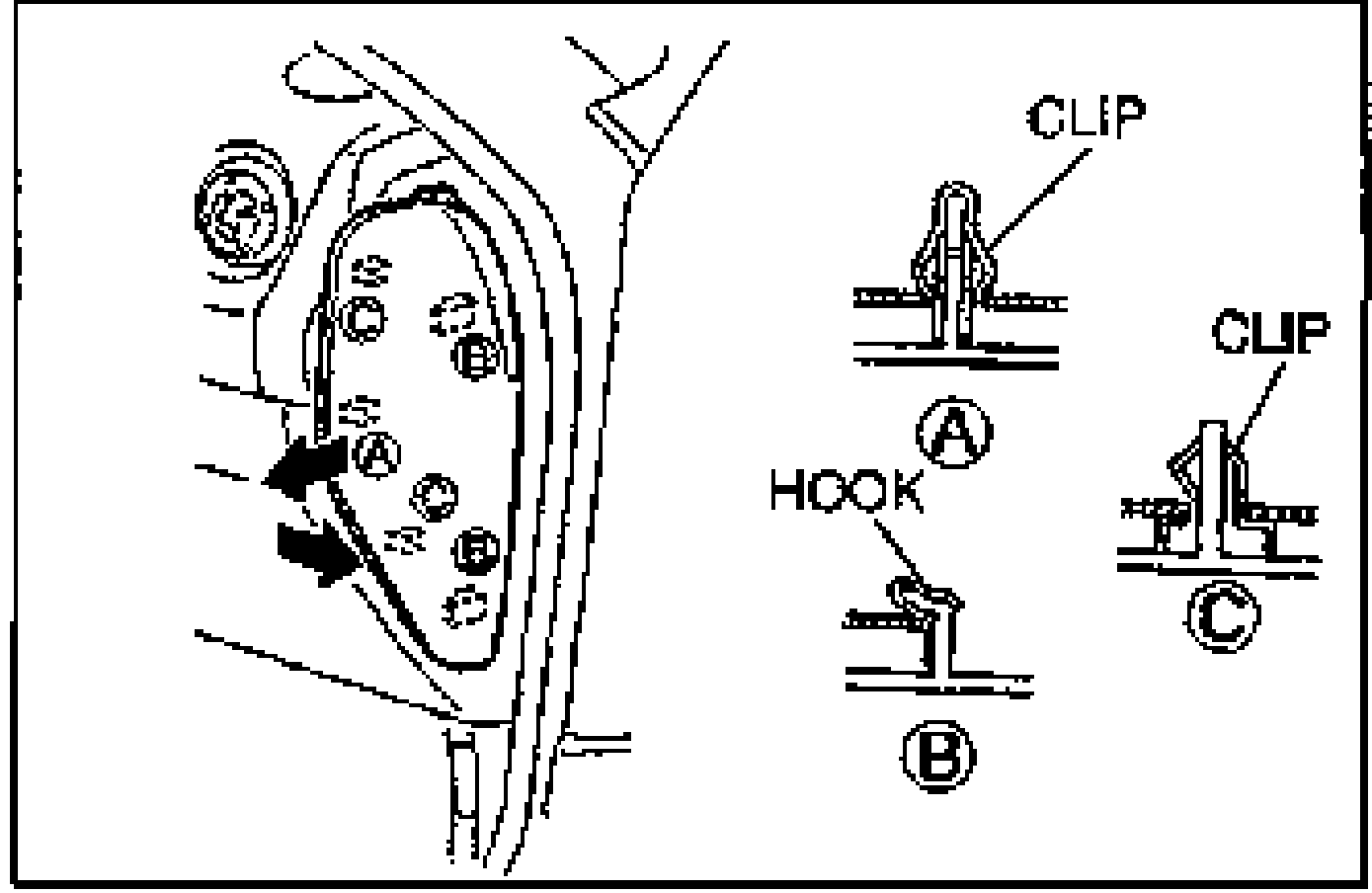
- 2Pull the side panel forward to remove the hook from the body.
Hood release lever
Loosen the hood release lever mounting nut.
Lower panel
- 1Remove the lower panel installation screws.
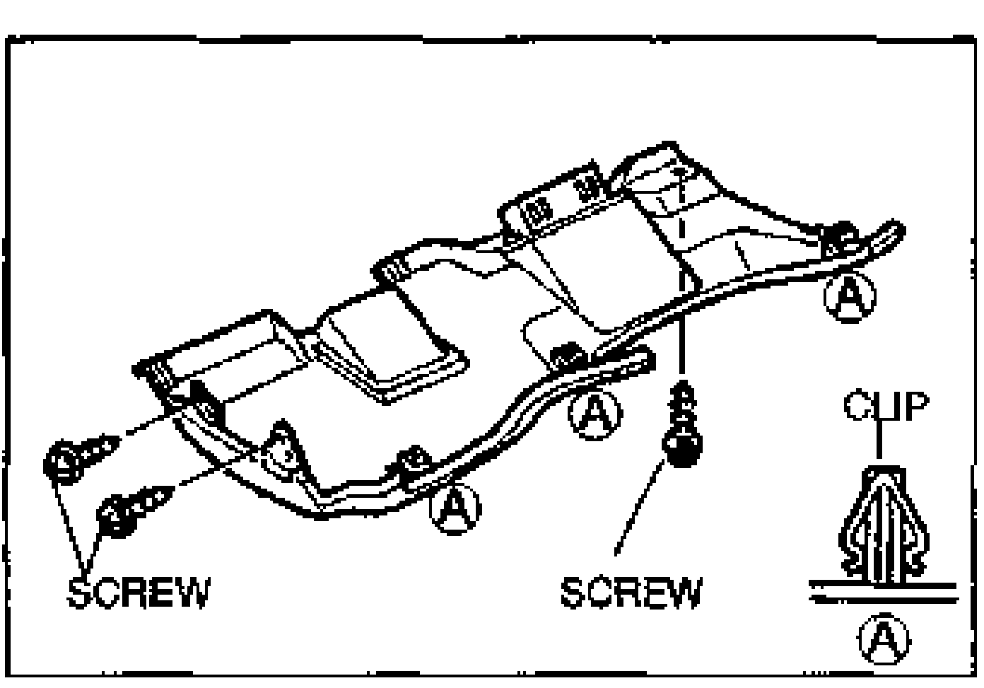
- 2Pull the lower panel forward to disengage the clips.
See also
1995 Body Electrical Troubleshooting Manual section Z4 · 1995 Body Electrical Troubleshooting Manual section C1