
LIFTGATE GLASS
S-47prose procedureLiftgate glass Installation note (continued)
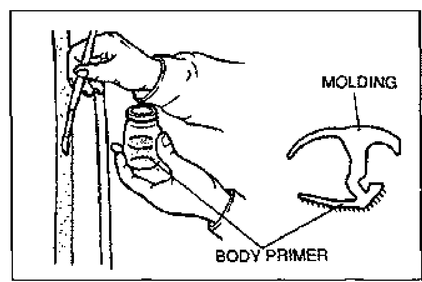
- 4Apply primer with a brush to the bonding area of the glass, body, and molding. Keep the area free of dirt and grease, and do not touch the surface. Allow the primer to dry for approximately 30 minutes.
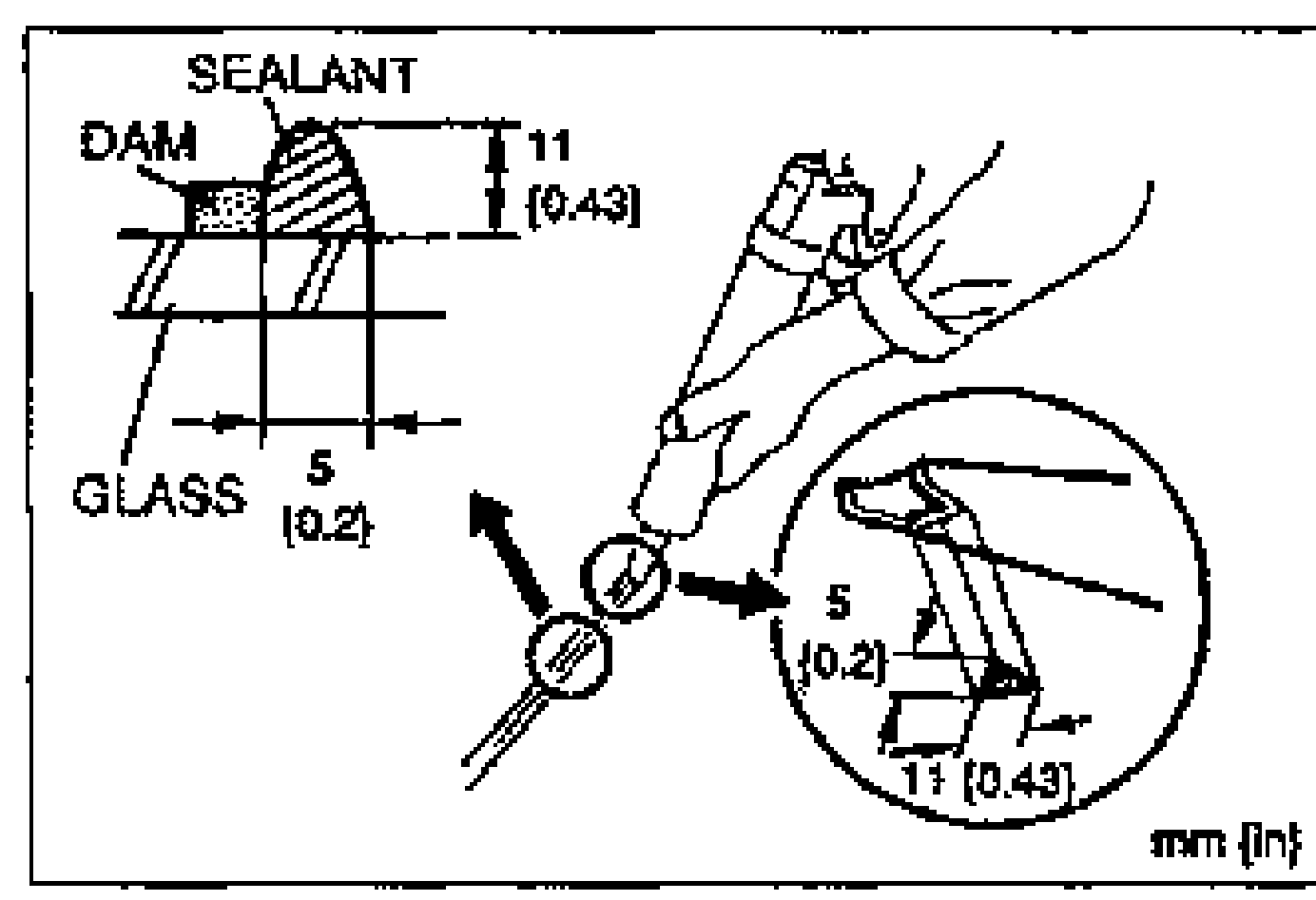
- 5After the primer has dried, apply an 11 mm {0.43 in} high bead of repair sealant around the circumference of the glass as shown. Keep the bead of sealant smooth and even, reshaping it with a spatula where necessary.
- 6Align the glass via the locating pin and bolts and install the glass onto the body. Verify that the clearance between the top of the glass and the liftgate is 8 mm {0.31 in}.
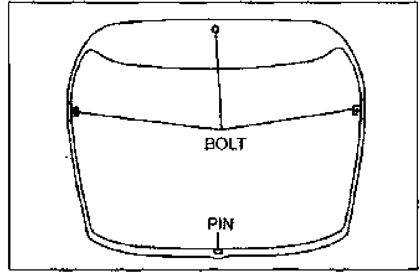
- 7Press firmly on the glass to compress the sealant and install the nuts onto the bolts.
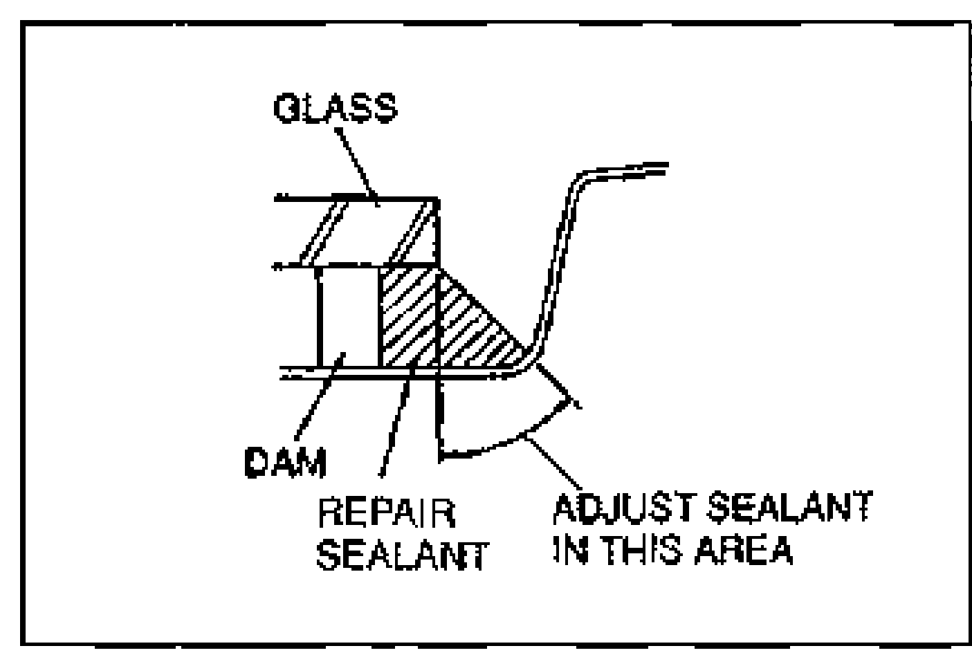
- 8Use a scraper to smooth away any sealant that oozes out. Add more sealant to any points of poor contact. Adjust the upper and side sealant as shown, if necessary.
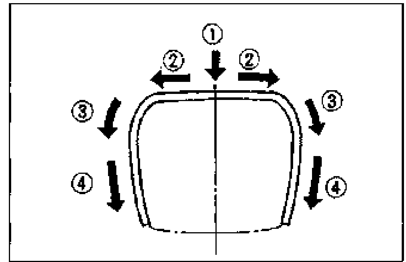
- 9Install the liftgate molding before the sealant hardens. (1) Align the mark on the glass to that on the molding. (2) Install the top of the molding. (3) Install the corners of the molding. (4) Install the sides of the molding, starting from the top and then toward the bottom.
| Specification | Value |
|---|---|
| {40—60 kgf·cm, 35—52 in·lbf} (nuts onto bolts, step 7) | 4.0-5.8N·m |
{40—60 kgf·cm, 35—52 in·lbf} (nuts onto bolts, step 7)
4.0-5.8N·m