
DIFFERENTIAL — DISASSEMBLY / INSPECTION / ASSEMBLY
J2-51parts diagramDIFFERENTIAL section disassembly/inspection/assembly.
Disassembly / Inspection / Assembly
- 1Before disassembly, inspect the backlash of the side gears and pinion gears, referring to Preinspection.
- 2Disassemble in the order shown in the figure, referring to Disassembly Note.
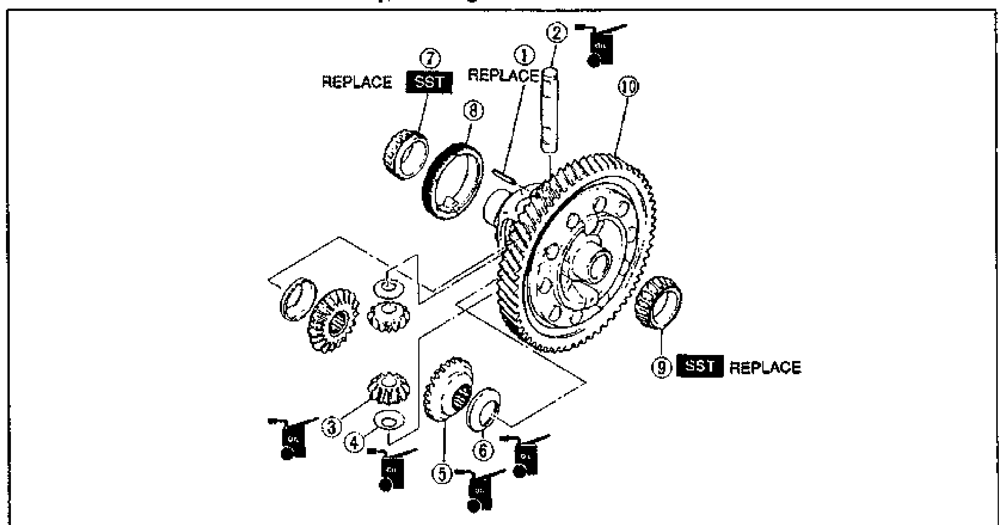
- 3Inspect all parts and repair or replace as necessary.
- 4Assemble in the reverse order of disassembly, referring to Assembly Note.
- 5Measure the backlash after assembly, referring to Backlash of Side Gear and Pinion Gear.
Differential parts legend
1
Part nameRoll pin
Note / ReferenceAssembly Note page J2-53
2
Part namePinion shaft
Note / Reference
3
Part namePinion gear
Note / ReferenceInspect for wear and cracks; Preinspection below; Inspection of backlash page J2-53
4
Part nameThrust washer
Note / Reference
5
Part nameSide gear
Note / ReferenceInspect for wear and cracks; Preinspection below; Inspection of backlash page J2-53
6
Part nameThrust washer
Note / Reference
7
Part nameBearing (side opposite ring gear)
Note / ReferenceDisassembly Note page J2-52; Inspection page J2-52; Assembly Note page J2-53
8
Part nameSpeedometer drive gear
Note / Reference
9
Part nameBearing (ring gear side)
Note / ReferenceDisassembly Note page J2-52; Inspection page J2-52; Assembly Note page J2-52
10
Part nameRing gear and gear case assembly
Note / ReferenceInspection page J2-52
Preinspection
Backlash of side gear and pinion gear
Measure the backlash by the following procedure.
Backlash of side gear and pinion gear
- 1Install the left and right drive shafts in the differential assembly.
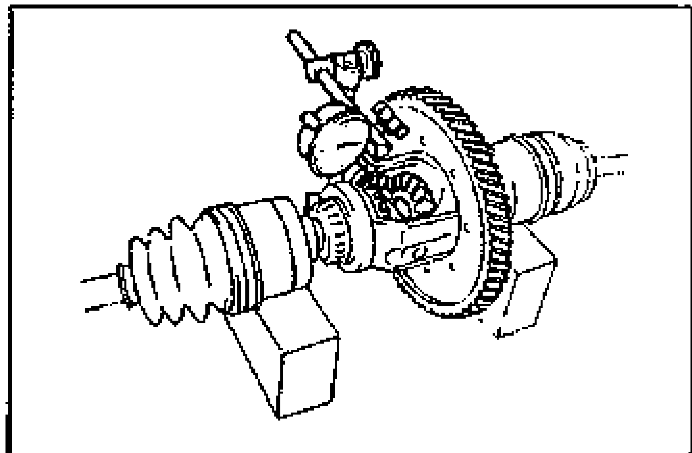
- 2Support the drive shafts on V-blocks as shown in the figure.
- 3Measure the backlash of both pinion gears.
- 4If not as specified, replace worn and damage parts.
| Specification | Value |
|---|---|
| Backlash (side gear and pinion gear) | 0-0.1mm {0-0.004 in} |
Backlash (side gear and pinion gear)
0-0.1mm {0-0.004 in}