
Transaxle Installation legend and Installation Notes
J2-47prose procedureManual transaxle (M/T) installation notes.
Transaxle Installation legend
1
Part nameTransaxle
Installation Notebelow
2
Part nameNo.4 engine mount
Installation Note
3
Part nameUndercover
Installation Note
4
Part nameEngine mounting member
Installation Notebelow
5
Part nameDrive shaft and joint shaft
Installation Notepage J2-48
6
Part nameDrive shaft
Installation Notepage J2-48
7
Part nameStabilizer control link
Installation Notepage J2-49
8
Part nameTie rod end
Installation Notepage J2-49
9
Part nameChange control rod
Installation Notepage J2-49
10
Part nameExtension bar
Installation Notepage J2-49
11
Part nameExhaust pipe
Installation Note
12
Part nameTransverse member
Installation Note
13
Part nameClutch release cylinder
Installation Note
14
Part nameVehicle speedometer sensor (speedometer driven gear)
Installation Note
15
Part nameBack-up light switch connector
Installation Notepage J2-49
16
Part nameNeutral switch connector
Installation Note
17
Part nameFuel filter
Installation Note
18
Part nameHarness bracket
Installation Note
19
Part nameStarter
Installation Note
20
Part nameBattery carrier
Installation Note
21
Part nameBattery
Installation Note
22
Part nameAir cleaner assembly
Installation Note
23
Part nameFresh-air duct
Installation Note
24
Part nameSplash shield
Installation Note
25
Part nameWheel and tire
Installation Note
Installation Note
Transaxle
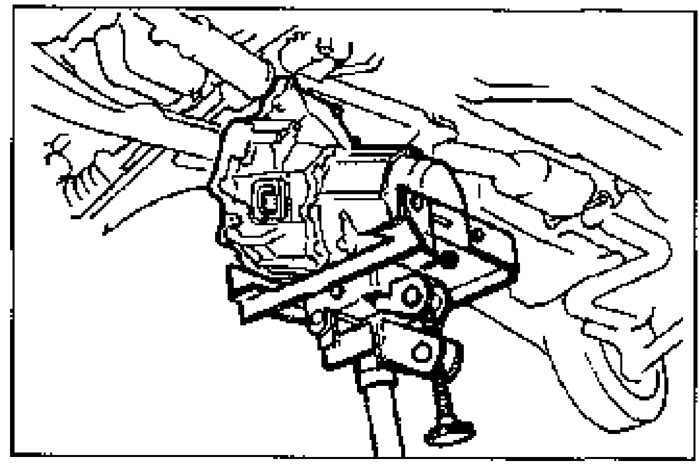
- 1Set the transaxle on a jack and lift it into place.
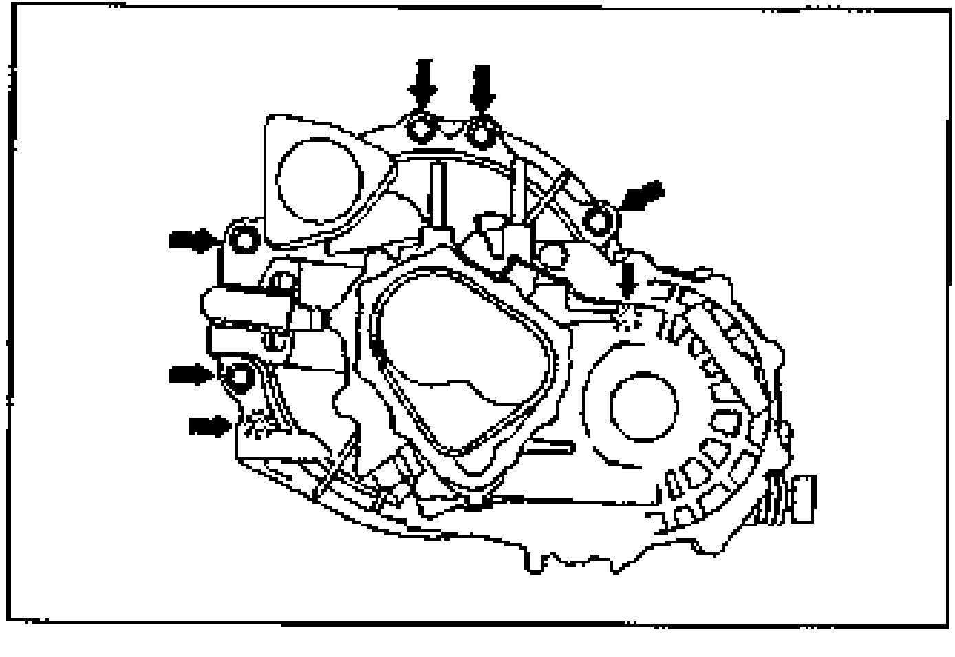
- 2Install the transaxle mounting bolts.
- 3Loosely tighten the No.4 engine mount bolts.
| Specification | Value |
|---|---|
| Transaxle mounting bolt | ≈667 - 971N·m |
Transaxle mounting bolt
667 - 971N·m
Engine mounting member
NOTE
Put the No.1 and No.2 engine mount stud bolts in the installing holes when installing the engine mounting member.
Engine mounting member
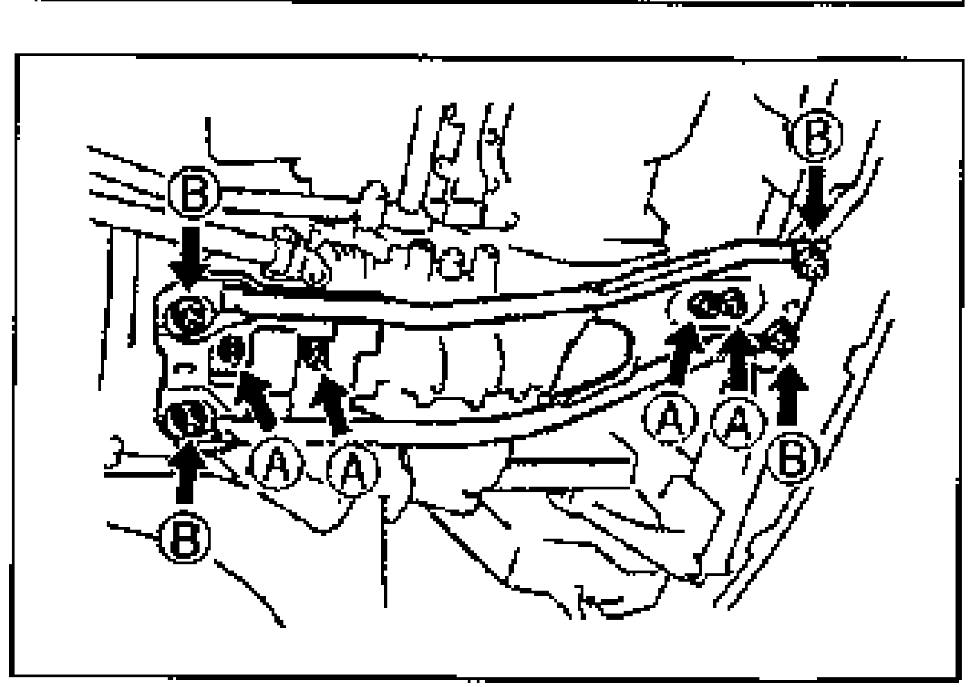
- 1Align the No.1 and No.2 engine mount stud bolts in the installing holes, and install the bolts and nuts as shown.
| Specification | Value |
|---|---|
| Engine mounting member tightening torque Alocation A | ≈373 - 500N·m |
| Engine mounting member tightening torque Blocation B | ≈628 - 873N·m |
Engine mounting member tightening torque Alocation A
373 - 500N·m
Engine mounting member tightening torque Blocation B
628 - 873N·m