
Transaxle Installation Notes (No.4 mount, drive shaft and joint shaft)
J2-48prose procedureManual transaxle (M/T) installation notes.
No.4 engine mount
- 2Tighten the No.4 engine mount nuts.
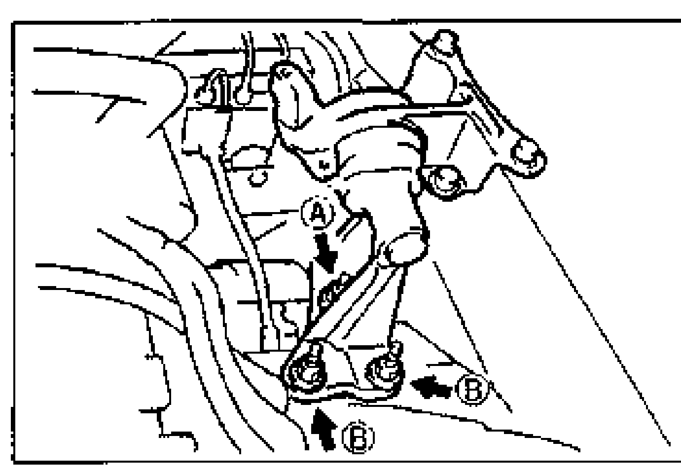
- 3Remove the SST (engine support).
| Specification | Value |
|---|---|
| No.4 engine mount nut tightening torque Alocation A | ≈657 - 912N·m |
| No.4 engine mount nut tightening torque Blocation B | ≈275 - 392N·m |
No.4 engine mount nut tightening torque Alocation A
657 - 912N·m
No.4 engine mount nut tightening torque Blocation B
275 - 392N·m
Drive shaft and joint shaft
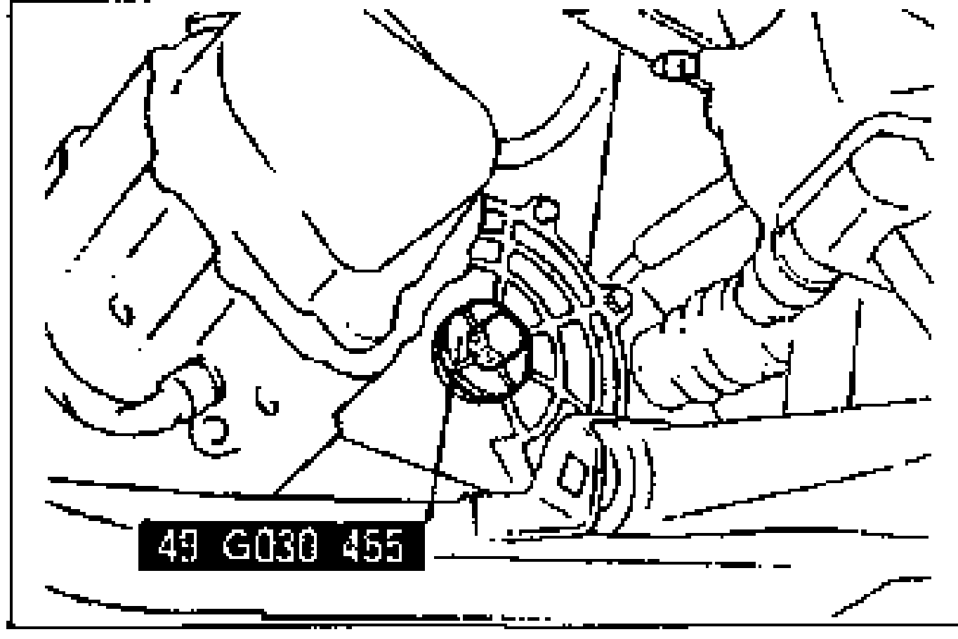
- 1Remove the SSTs from the transaxle case.
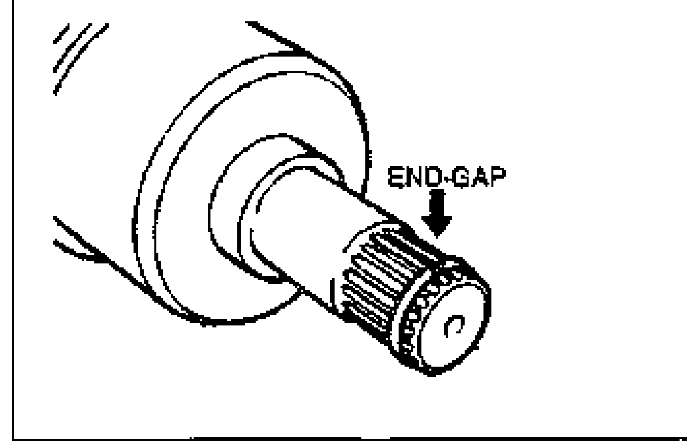
- 2Install the clip with the gap at the top of the groove.
- 3Apply transaxle oil to the oil seal lip, and install the drive shaft.Caution: The sharp edges of the drive shaft snap ring can slice or puncture the oil seal. Be careful when installing the drive shaft to the transaxle.
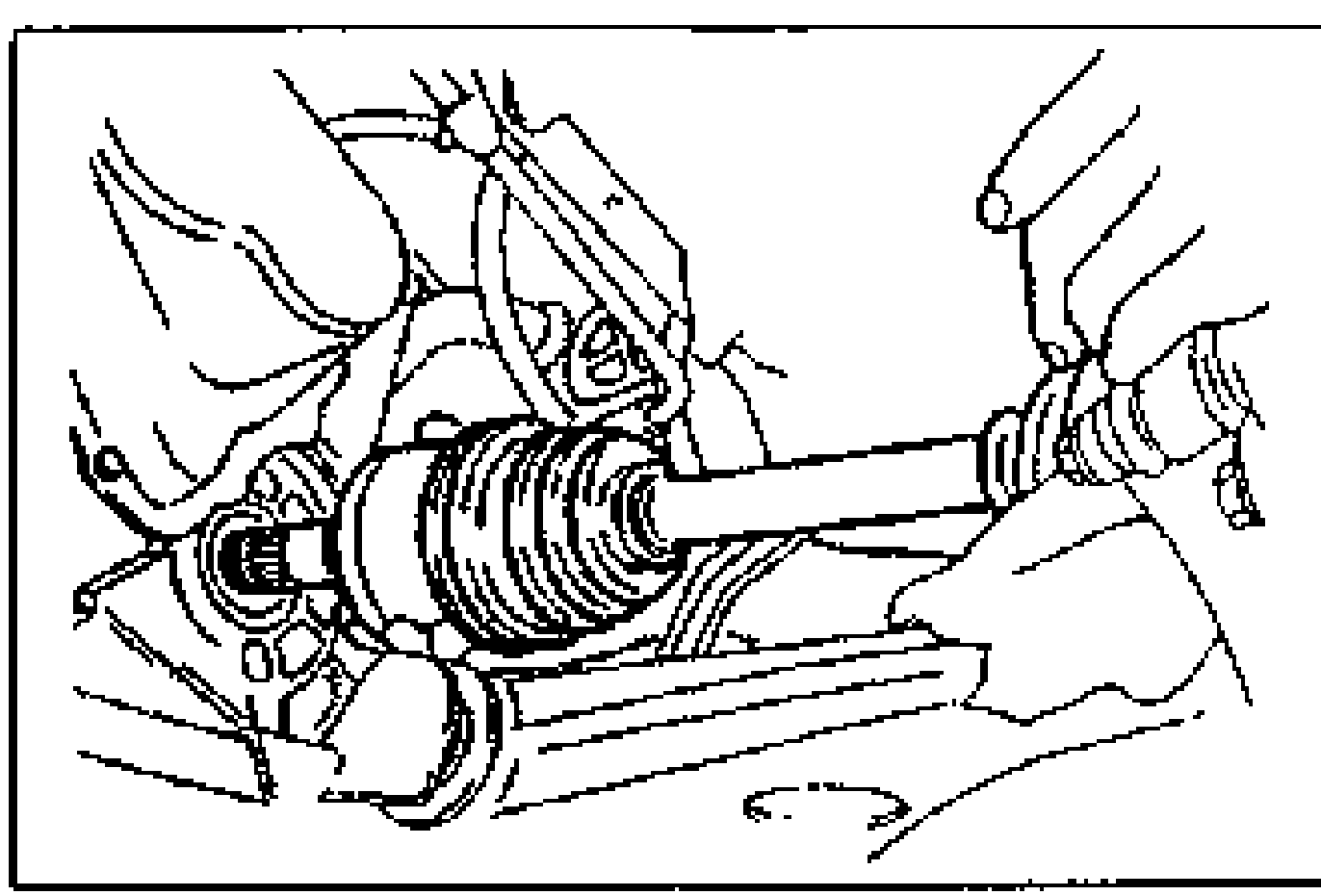
- 4Verify that the drive shaft is correctly seated by pulling on the shaft. It must not slide out.
- 5Insert the joint shaft to the transaxle.
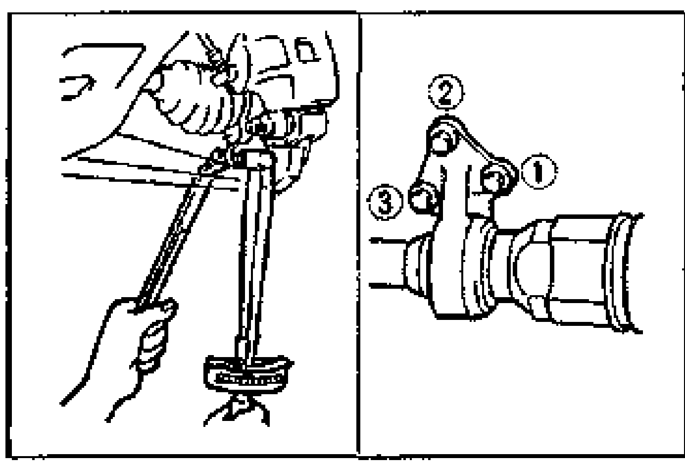
- 6Install the joint shaft to the cylinder block in the order shown.
- 7Connect the lower arm to the knuckle and tighten the clinch bolt.
| Specification | Value |
|---|---|
| Joint shaft to cylinder block bolt | ≈422 - 598N·m |
| Lower arm to knuckle clinch bolt | ≈431 - 569N·m |
Joint shaft to cylinder block bolt
422 - 598N·m
Lower arm to knuckle clinch bolt
431 - 569N·m