TRANSAXLE — 5th/Reverse Gear parts legend; Preinspection & Disassembly Note (Locknut)
J2-17prose procedureManual transaxle (M/T) 5th/Reverse gear disassembly continuation.
5th / Reverse Gear and Housing Parts — numbered legend
1
PartRear cover
Reference
2
PartLocknut (primary shaft)
ReferenceDisassembly Note below
3
PartLocknut (secondary shaft)
ReferenceDisassembly Note below
4
PartPrimary reverse synchronizer gear
ReferenceInspection page J2-27
5
PartReverse synchronizer ring
ReferenceInspection page J2-27
6
PartSecondary reverse synchronizer gear
ReferenceInspection page J2-27
7
Part5th/reverse shift fork
Reference
8
Part5th/reverse clutch hub assembly
ReferenceInspection page J2-27
9
Part5th synchronizer ring
ReferenceInspection page J2-27
10
Part5th gear
ReferencePreinspection below; Inspection page J2-27
11
PartGear sleeve
ReferenceInspection page J2-28
12
PartSecondary 5th gear
ReferenceInspection page J2-27
13
PartLock bolt
Reference
14
PartGuide bolt and washer
Reference
15
PartLock bolt, ball and spring
Reference
16
PartBack-up light switch
Reference
17
PartNeutral switch
Reference
18
PartTransaxle case assembly
Reference
19
PartMagnet
Reference
20
PartReverse idler shaft
Reference
21
PartReverse idler gear
ReferenceInspection page J2-27
22
Part5th/reverse shift rod
Reference
23
Part5th/reverse shift rod end
Reference
24
PartPin
Reference
25
PartCrank lever shaft
Reference
26
PartCrank lever assembly
Reference
27
PartShift fork and control rod assembly
ReferenceDisassembly Note page J2-18
28
PartSteel ball
Reference
29
PartSpring
Reference
30
PartPrimary shaft gear assembly
Reference
31
PartSecondary shaft gear assembly
Reference
32
PartDifferential assembly
Reference
33
PartClutch housing
Reference
34
PartSynchronizer key spring
Reference
35
PartClutch hub sleeve
Reference
36
PartSynchronizer key
Reference
37
PartClutch hub
Reference
38
Part3rd/4th shift fork
Reference
39
PartInterlock sleeve
Reference
40
PartControl lever
Reference
41
Part1st/2nd shift fork
Reference
42
PartControl rod
Reference
43
PartControl end
Reference
Preinspection
5th gear thrust clearance
- 1Measure the 5th gear thrust clearance by using a dial indicator.
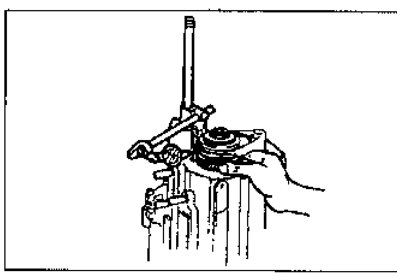
- 2If the clearance exceeds the maximum, check the contact surfaces of 5th gear and the clutch hub. Replace worn or damaged parts.
| Specification | Value |
|---|---|
| Clearance5th gear thrust clearance | 0.10—0.22mm {0.004—0.009 in} |
| Maximum5th gear thrust clearance | 0.27mm {0.011 in} |
Clearance5th gear thrust clearance
0.10—0.22mm {0.004—0.009 in}
Maximum5th gear thrust clearance
0.27mm {0.011 in}
Disassembly note
Locknut
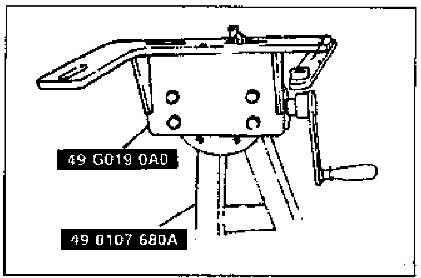
- 1Mount the transaxle on the SSTs.