
Transaxle Assembly Notes (shift rod, crank lever, reverse idler)
J2-44prose procedureManual transaxle (M/T) assembly notes.
Shift rod and control end coupling
- 2Insert the spring seat and spring into the reverse lever shaft, install the steel ball, and place a scraper against it.
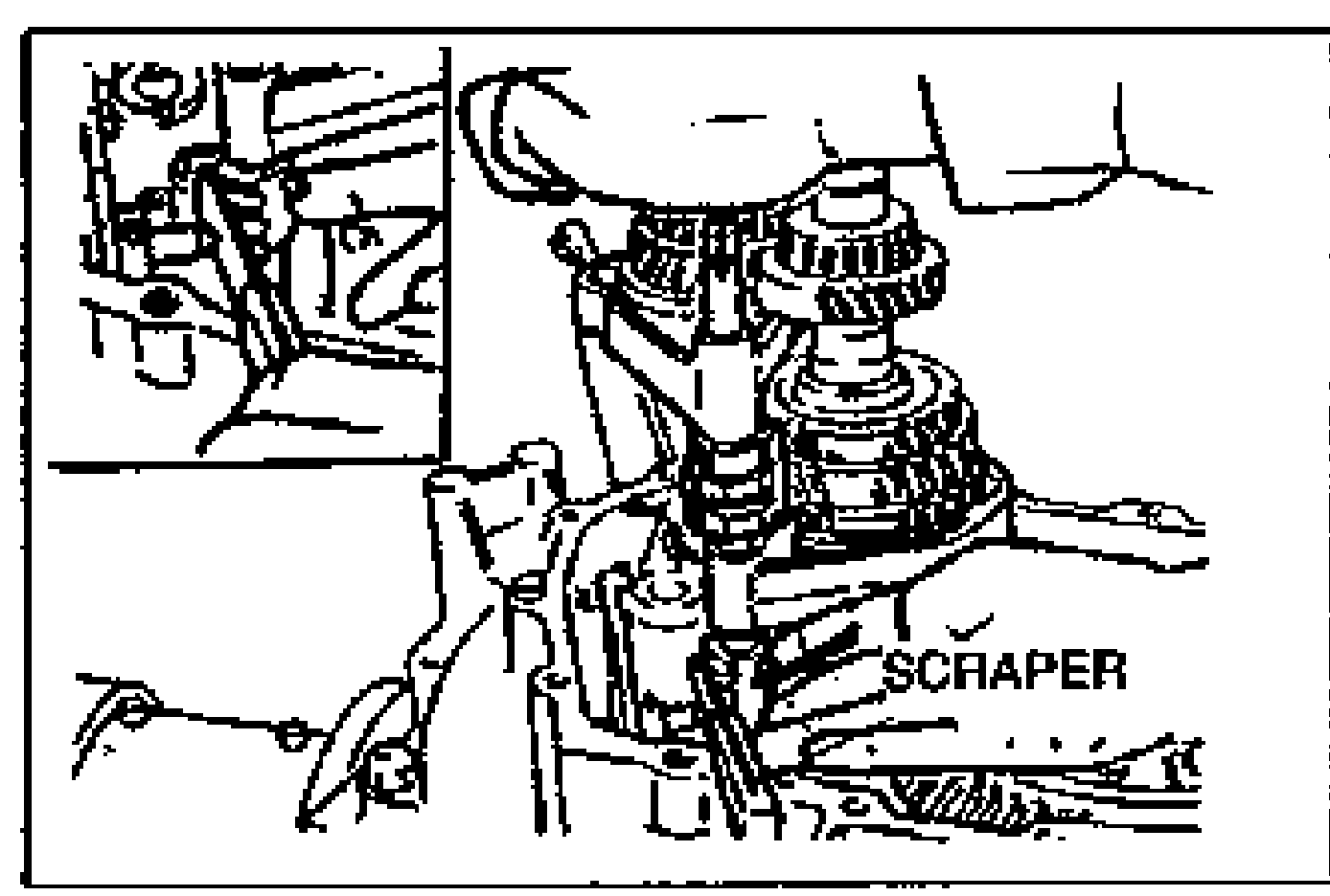
- 3With the edge of the control end against the scraper, push the control end in the direction of the arrow so that the ball goes into the shaft. This will line up the rod with the shift rod coupling hole in the clutch housing.
- 4Set each clutch hub sleeve to the neutral position, and tap the shift rod from above so that the steel ball goes into the center groove (of the three grooves in the control end).
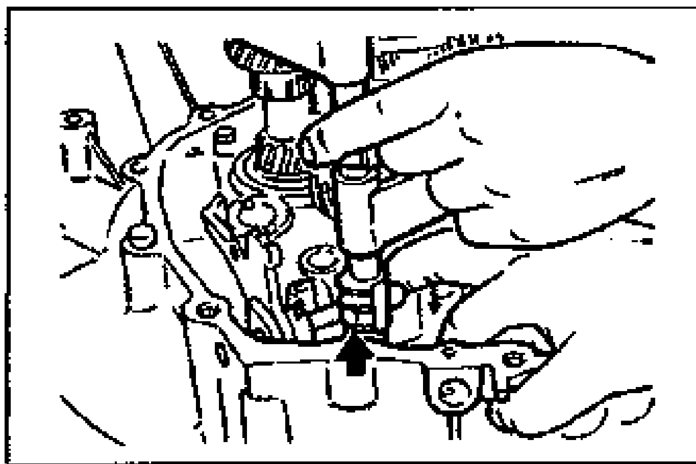
- 5Pull the ball part of the control end forward so that the steel ball goes into the detent in the groove.
Crank lever assembly and crank lever shaft
- 1Install a new O-ring to the crank lever shaft.
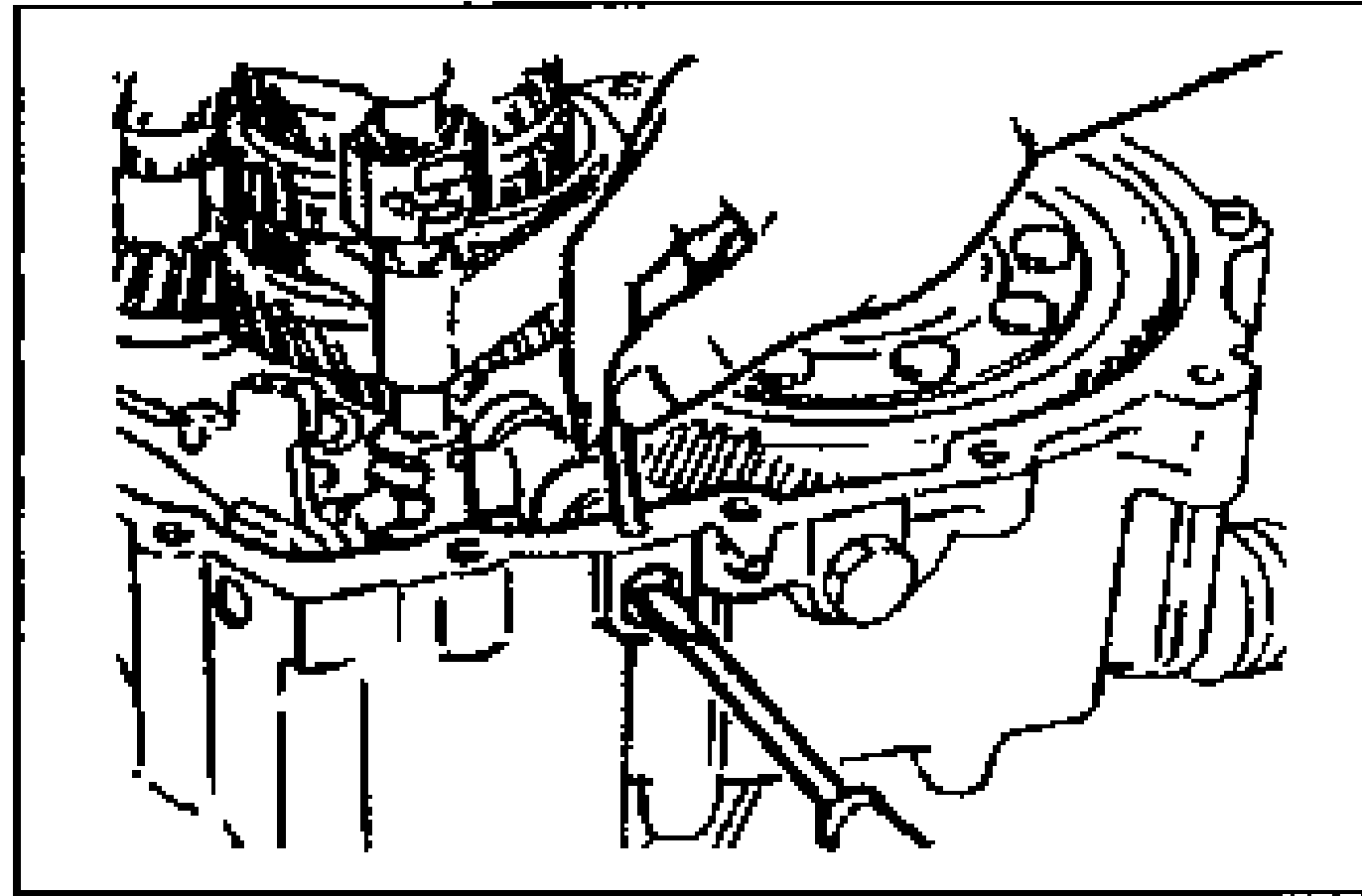
- 2Fit the crank lever between the change arm and the control end, and connect the crank lever shaft to the crank lever.
- 3Align the pin holes of the crank lever shaft and the clutch housing, and insert a new pin.
5th/reverse shift rod end and 5th/reverse shift rod
- 1Install shift rod end (1) and the shift rod (2), and tighten the gate mounting bolt.
| Specification | Value |
|---|---|
| Gate mounting bolt | ≈116 - 134N·m |
Gate mounting bolt
116 - 134N·m
Reverse idler gear and reverse idler shaft
- 1Install the reverse idler gear and the reverse idler shaft.
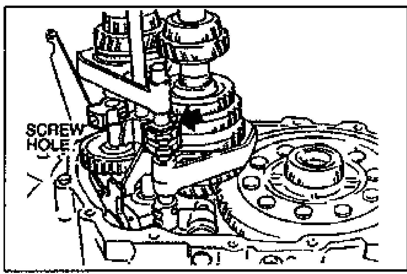
- 2Attach the magnet to the clutch housing.
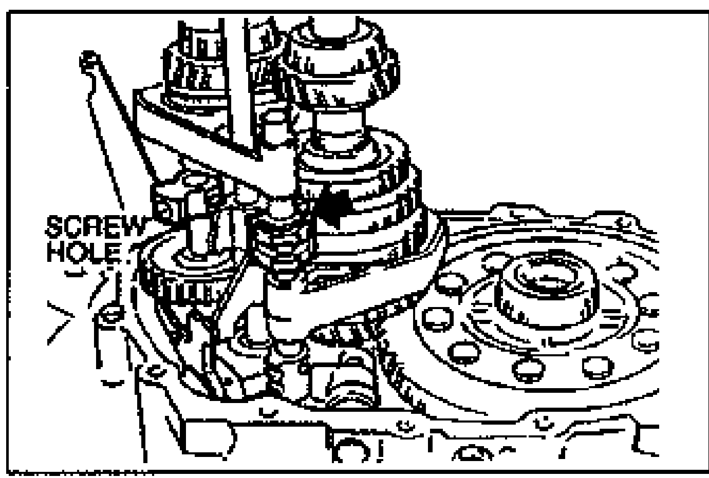
- 3Align the end of the interlock sleeve with the control lever (arrow), and face the reverse idler shaft screw hole in the direction shown in the figure.