
Transaxle INSTALLATION
J2-46parts diagramManual transaxle (M/T) installation. Diagram references lettered mount locations A-F.
Installation
- 1On level ground, raise the vehicle and support it evenly on safety stands.
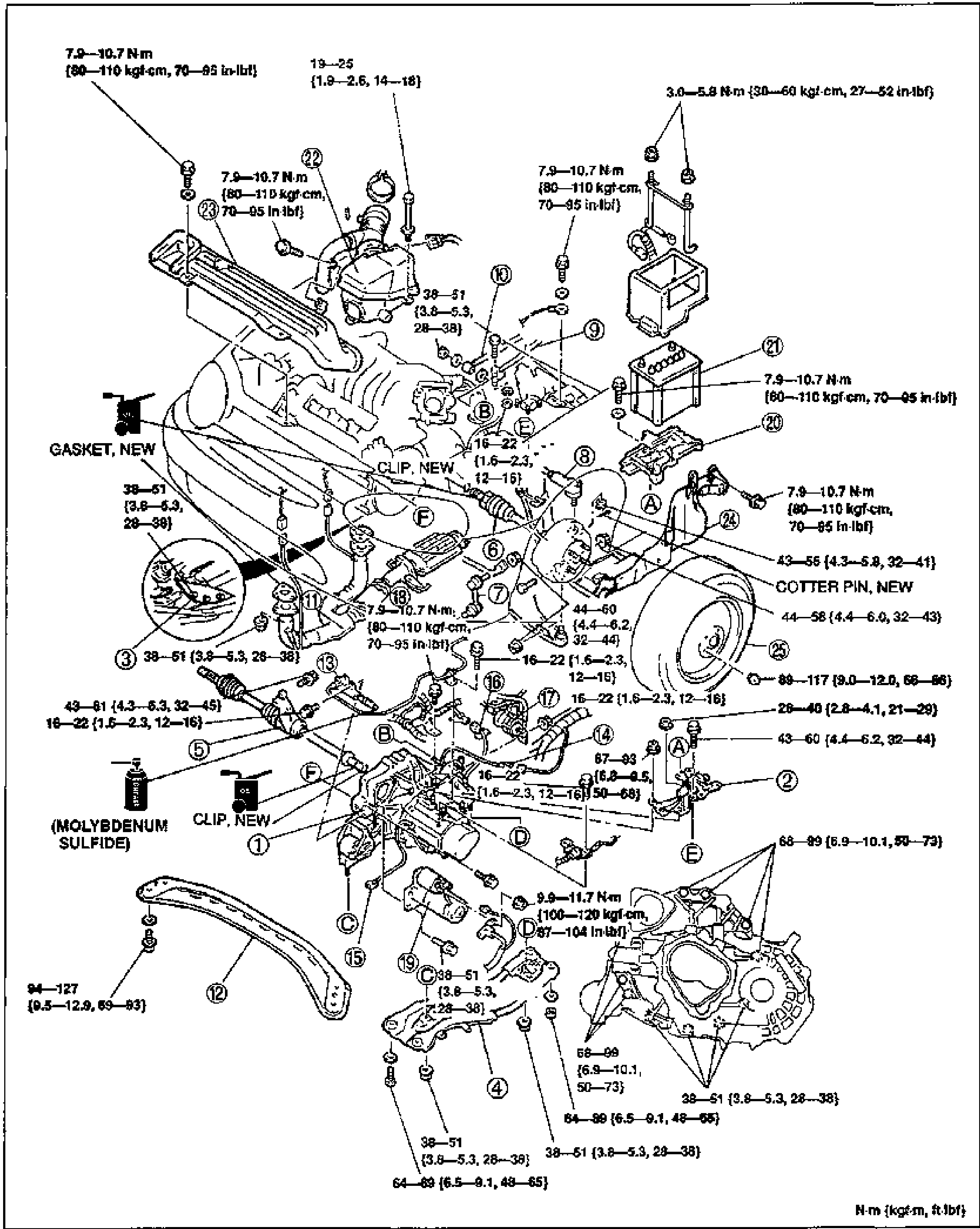
- 2Install in the order shown in the figure, referring to Installation Note.
- 3Add the specified amount and type of transaxle oil. (Refer to page J2-7.)
- 4Warm up the engine and transaxle, inspect for oil leakage, and check transaxle operation.
| Specification | Value |
|---|---|
| Boltmultiple locations | 7.9-10.7N·m {80-110 kgf-cm, 70-95 in-lbf} |
| Bolt | 19-25N·m {1.9-2.6 m-kg, 14-18 ft-lbf}3.0-5.8N·m {30-60 kgf-cm, 27-52 in-lbf} |
| Boltmultiple locations | 38-51N·m {3.8-5.3 m-kg, 28-38 ft-lbf}16-22N·m {1.6-2.3 m-kg, 12-16 ft-lbf} |
| Bolt | 43-55N·m {4.3-5.8 m-kg, 32-41 ft-lbf}43-58N·m {4.4-6.0 m-kg, 32-43 ft-lbf}43-61N·m {4.3-6.3 m-kg, 32-45 ft-lbf}44-60N·m {4.4-6.2 m-kg, 32-44 ft-lbf} |
| Boltcallout 25 | 89-117N·m {9.0-12.0 m-kg, 66-86 ft-lbf} |
| Bolt | 28-40N·m {2.8-4.1 m-kg, 21-29 ft-lbf}67-93N·m {6.8-9.5 m-kg, 50-68 ft-lbf} |
| Boltmultiple locations | 68-99N·m {6.9-10.1 m-kg, 50-73 ft-lbf} |
| Boltfront member, callout 12 | 94-127N·m {9.5-12.9 m-kg, 69-93 ft-lbf} |
| Boltlocation D | 9.9-11.7N·m {100-120 kgf-cm, 87-104 in-lbf} |
| Boltmultiple locations | 64-89N·m {6.5-9.1 m-kg, 48-65 ft-lbf} |
Boltmultiple locations
7.9-10.7N·m {80-110 kgf-cm, 70-95 in-lbf}
Bolt
19-25N·m {1.9-2.6 m-kg, 14-18 ft-lbf}3.0-5.8N·m {30-60 kgf-cm, 27-52 in-lbf}
Boltmultiple locations
38-51N·m {3.8-5.3 m-kg, 28-38 ft-lbf}16-22N·m {1.6-2.3 m-kg, 12-16 ft-lbf}
Bolt
43-55N·m {4.3-5.8 m-kg, 32-41 ft-lbf}43-58N·m {4.4-6.0 m-kg, 32-43 ft-lbf}43-61N·m {4.3-6.3 m-kg, 32-45 ft-lbf}44-60N·m {4.4-6.2 m-kg, 32-44 ft-lbf}
Boltcallout 25
89-117N·m {9.0-12.0 m-kg, 66-86 ft-lbf}
Bolt
28-40N·m {2.8-4.1 m-kg, 21-29 ft-lbf}67-93N·m {6.8-9.5 m-kg, 50-68 ft-lbf}
Boltmultiple locations
68-99N·m {6.9-10.1 m-kg, 50-73 ft-lbf}
Boltfront member, callout 12
94-127N·m {9.5-12.9 m-kg, 69-93 ft-lbf}
Boltlocation D
9.9-11.7N·m {100-120 kgf-cm, 87-104 in-lbf}
Boltmultiple locations
64-89N·m {6.5-9.1 m-kg, 48-65 ft-lbf}