
Transaxle Assembly Notes (case, secondary 5th gear, clutch hub, locknut)
J2-45prose procedureManual transaxle (M/T) assembly notes.
Transaxle case assembly
- 1Apply a thin coat of sealant to the contact surfaces of the clutch housing and transaxle case, and tighten the transaxle case installation bolts to the specified torque.
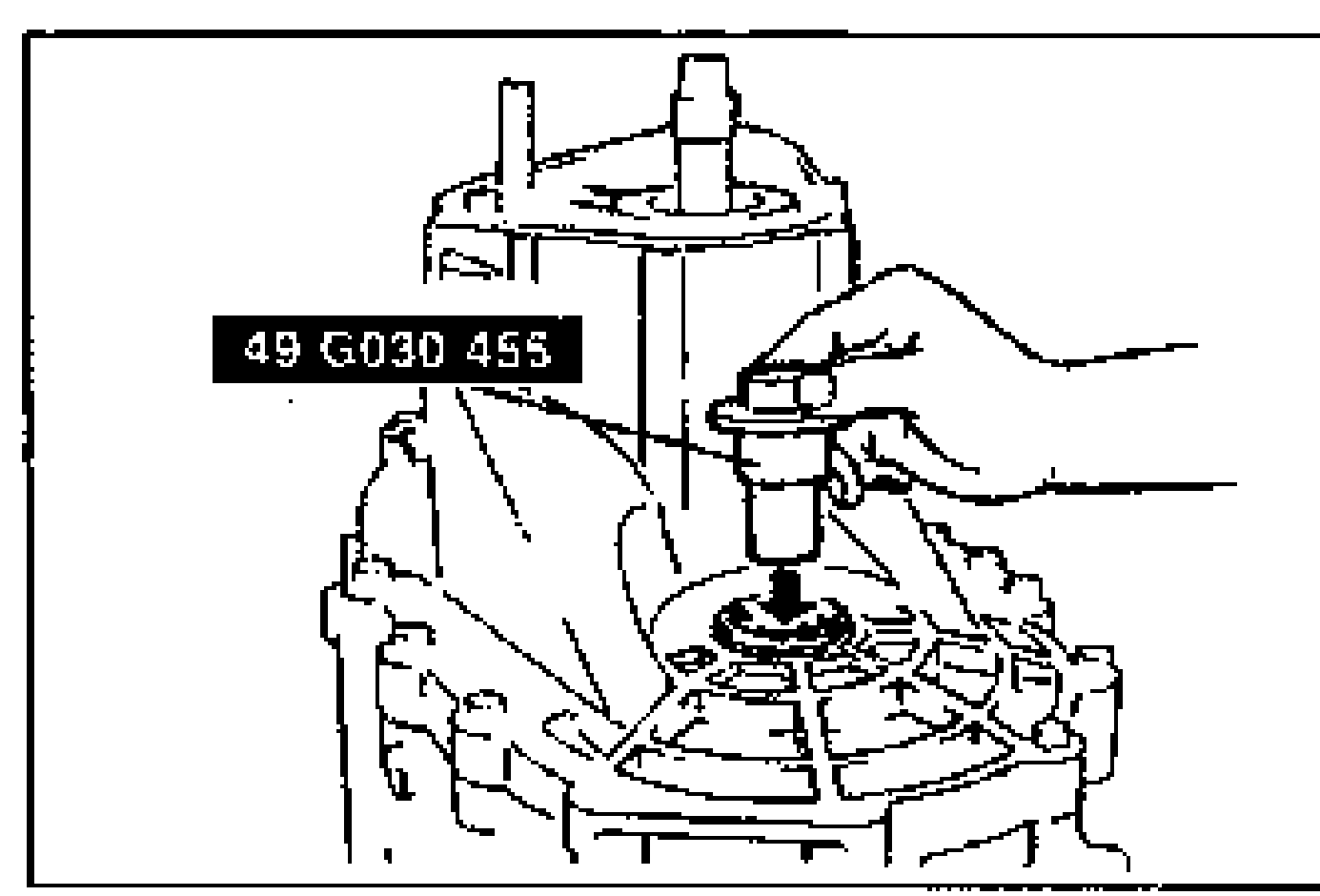
- 2Insert the SSTs through the drive shaft and joint shaft hole.
| Specification | Value |
|---|---|
| Transaxle case installation bolt | ≈373 - 500N·m |
Transaxle case installation bolt
373 - 500N·m
Secondary 5th gear
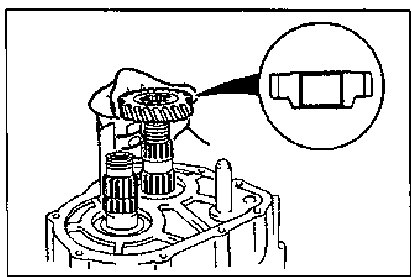
- 1Install the secondary 5th gear as shown.
5th/reverse clutch hub assembly and 5th/reverse shift fork
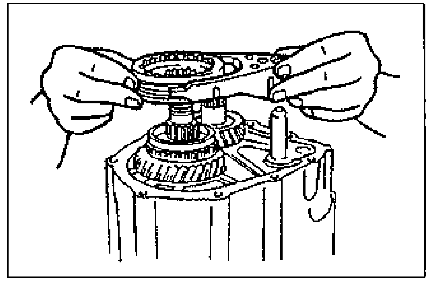
- 1Install the 5th/reverse clutch hub assembly and the 5th/reverse shift fork together.
Locknut
- 1Shift to 1st gear.
- 2Lock the primary shaft by using the SST.
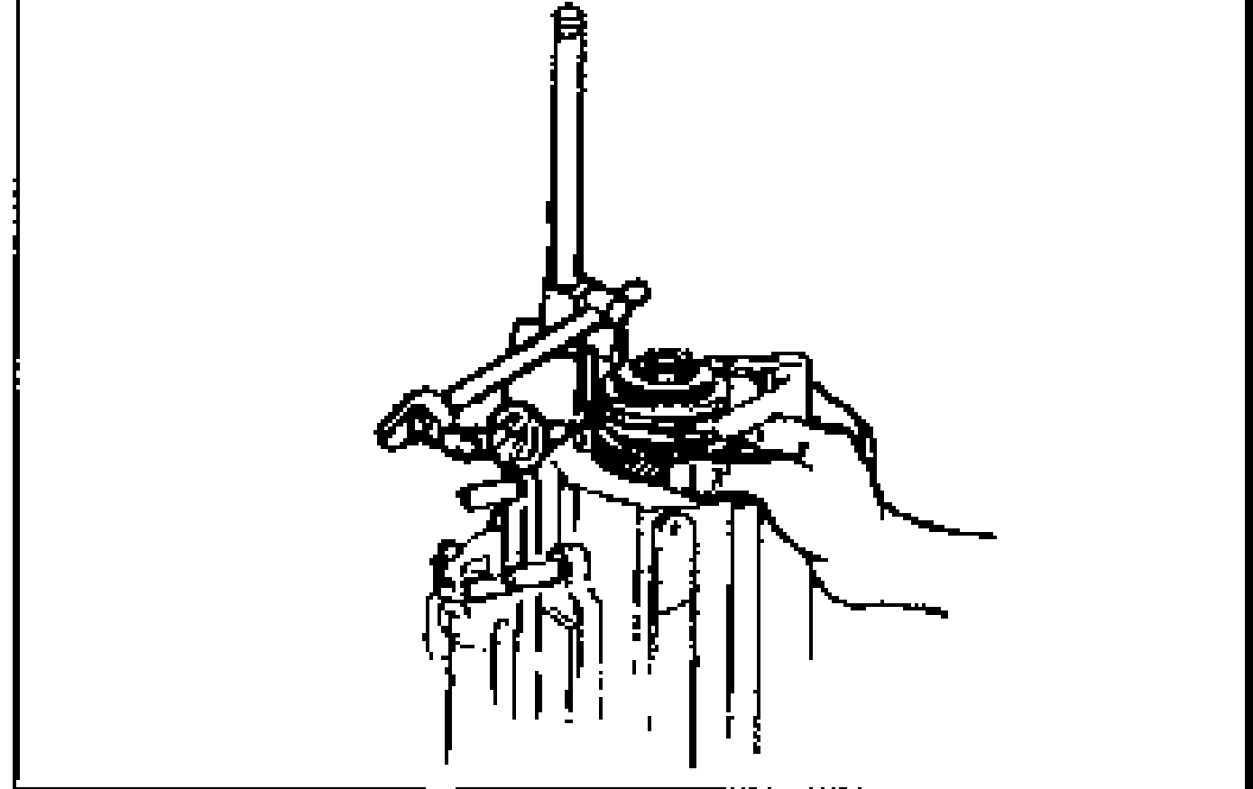
- 3Tighten new locknuts onto the primary and secondary shafts.
- 4Stake the locknuts.
- 5Measure the 5th gear thrust clearance by using a dial indicator.
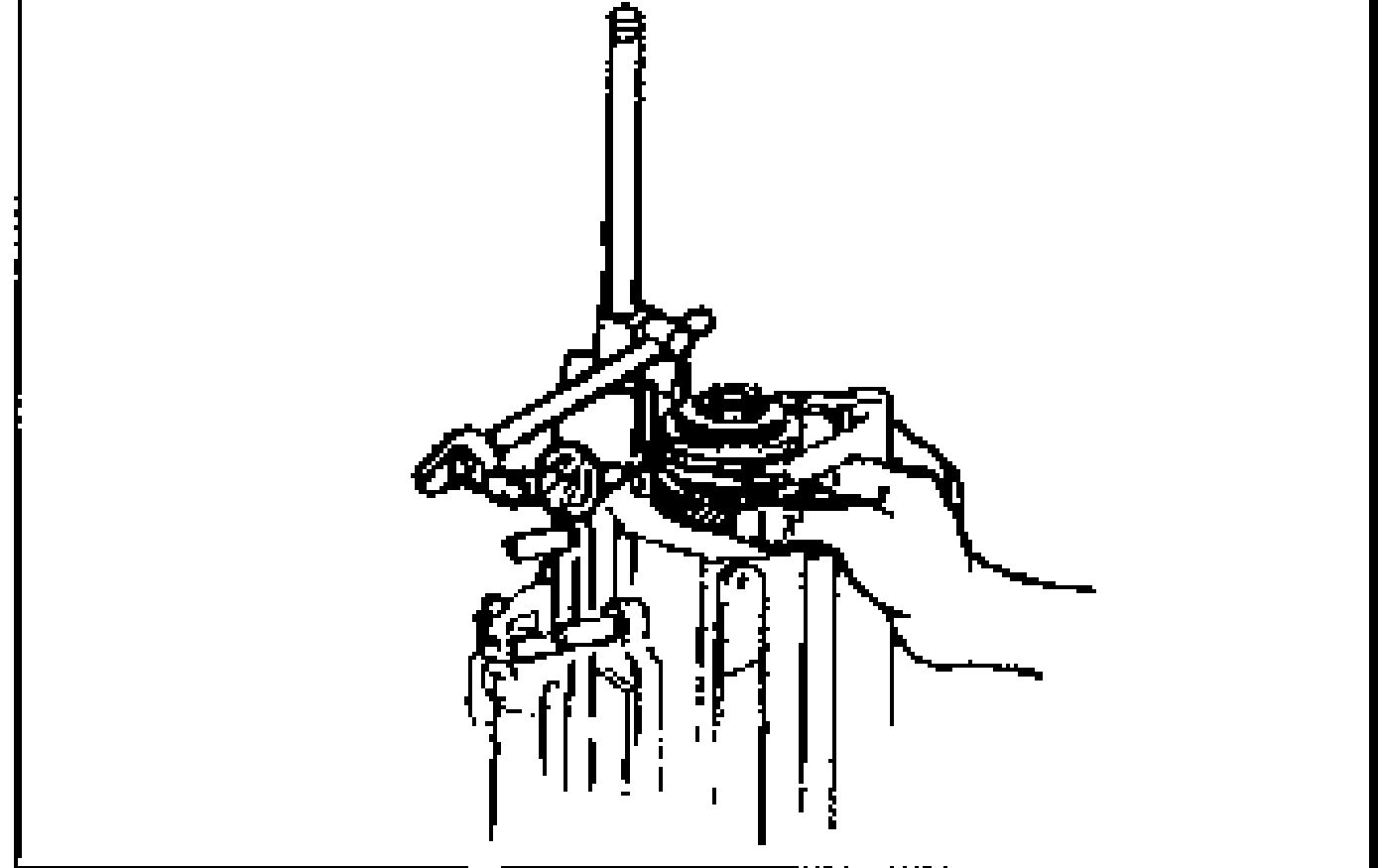
- 6If not as specified, reassemble the transaxle.
| Specification | Value |
|---|---|
| Locknut tightening torque (primary and secondary shafts) | ≈1255 - 1922N·m |
| 5th gear thrust clearancestandard | 0.10-0.22mm {0.004-0.009 in} |
| 5th gear thrust clearancemaximum | 0.27mm {0.011 in} |
Locknut tightening torque (primary and secondary shafts)
1255 - 1922N·m
5th gear thrust clearancestandard
0.10-0.22mm {0.004-0.009 in}
5th gear thrust clearancemaximum
0.27mm {0.011 in}