
Engine Speed Sensing Power Steering — Drive Belt (K8 DOHC)
N-52spec tableK8 DOHC engine drive belt. Routing includes idle pulley and water pump pulley.
DRIVE BELT (K8 DOHC)
Inspection
Drive belt inspection
- 1Check the drive belt for wear, cracks, and fraying. Replace as necessary.
- 2Verify that the drive belts are correctly mounted on the pulleys.
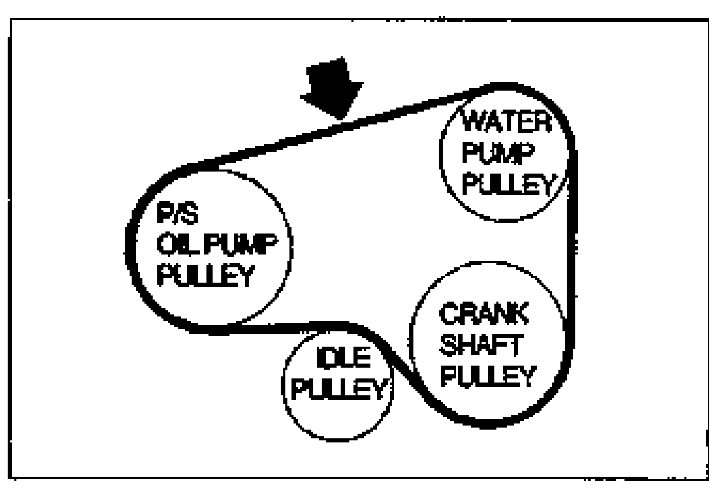
- 3Check the drive belt deflection when the engine is cold, or at least 30 minutes after the engine has stopped. Apply moderate pressure (98 N {10 kgf, 22 lbf}) midway between the specified pulleys.
- 4If the deflection is not within specification, adjust it.
Deflection
Deflection mm{in}
6.0-7.0 {0.24-0.27}
Used7.0-8.0 {0.28-0.31}
Limit9.0 {0.35}
NOTE
* A belt that has been on a running engine for less than five minutes.
Drive belt tension check
- 1Belt tension can be checked in place of belt deflection. Check the drive belt tension when the engine is cold, or at least 30 minutes after the engine has stopped. Using the SST, check the belt tension between any two pulleys.
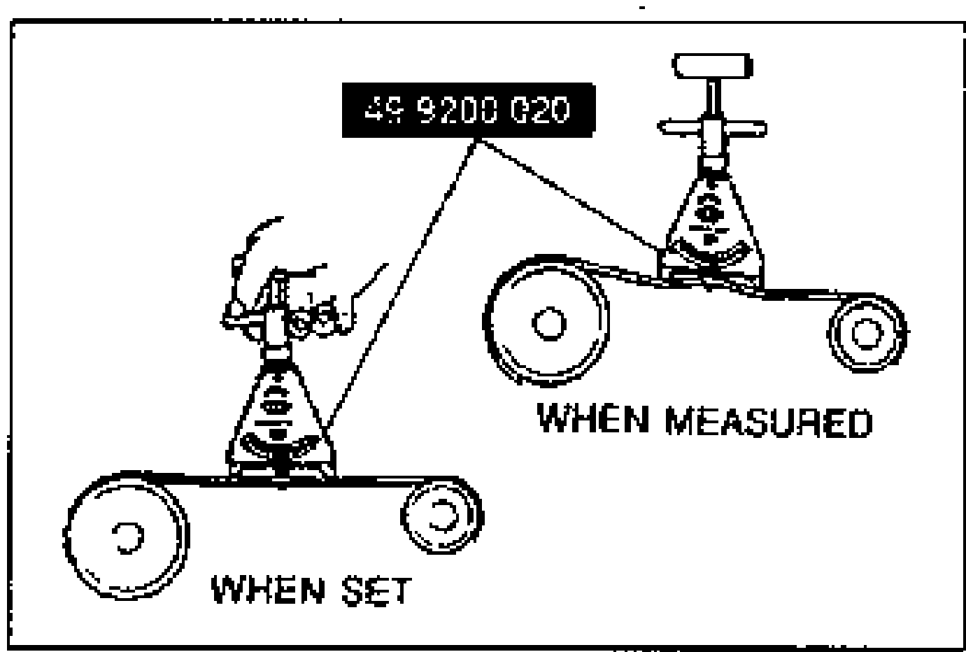
- 2If the tension is not within specification, adjust it.
Tension
Tension N{kgf·lbf}
540-686 {55-70, 130-154}
Used392-539 {40-55, 88-121}
Limit343 {35, 77}
NOTE
* A belt that has been on a running engine for less than five minutes.
Adjustment
Drive belt adjustment
- 1Loosen locknut (A). Turn adjusting bolt (B) to adjust the belt to the specified deflection and tension.
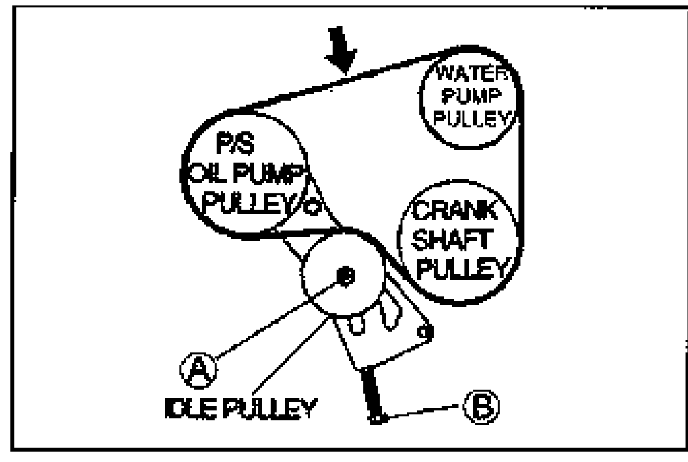
- 2Tighten locknut (A) to the specified torques.
| Specification | Value |
|---|---|
| Tightening torque - Nut A | ≈314 - 451N·m |
Tightening torque - Nut A
314 - 451N·m
Replacement
Drive belt replacement
- 1Remove the alternator and A/C drive belt. (Refer to body electrical troubleshooting manual, section G.)
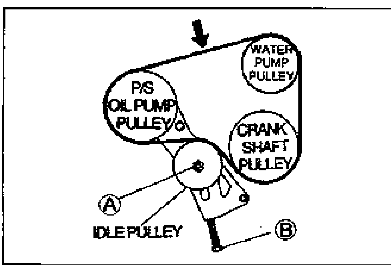
- 2Loosen locknut (A).
- 3Turn adjusting bolt (B) to release the belt tension.
- 4Remove the belt.
- 5Install a new P/S drive belt and adjust the tension and deflection. (Refer to above for adjustment.)
- 6Install A/C drive belt and adjust the tension and deflection. (Refer to body electrical troubleshooting manual, section G.)