
Engine Speed Sensing Power Steering — Support Yoke / Adjusting Cover / Tie Rod
N-41prose procedureEngine speed sensing power steering — support yoke, pinion preload via adjusting cover, tie rod installation.
17. Support yoke
- 1(1) Secure the gear housing in a vise so that the support yoke position faces upward.
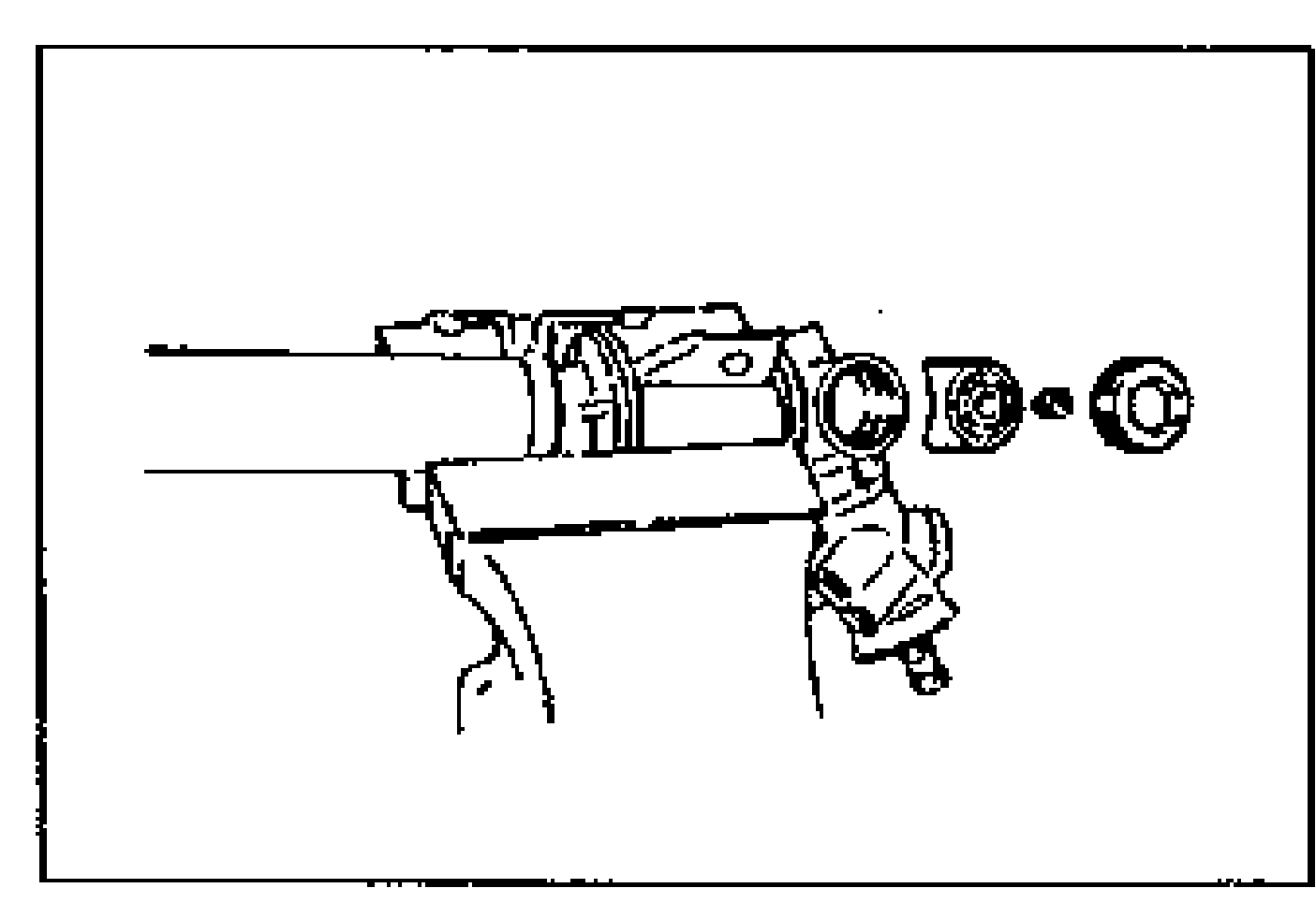
- 2(2) Apply grease (lithium base NLGI No.2) to the rack sliding surface of the pressure pad, then install it in the housing.
- 3(3) Install the support yoke.
- 4(4) Install the yoke spring.
18. Adjusting cover
- 1(1) Set the rack in the center position.
- 2(2) Apply sealant to the adjusting cover.
- 3(3) Set the SSTs and a torque wrench against the adjusting cover.
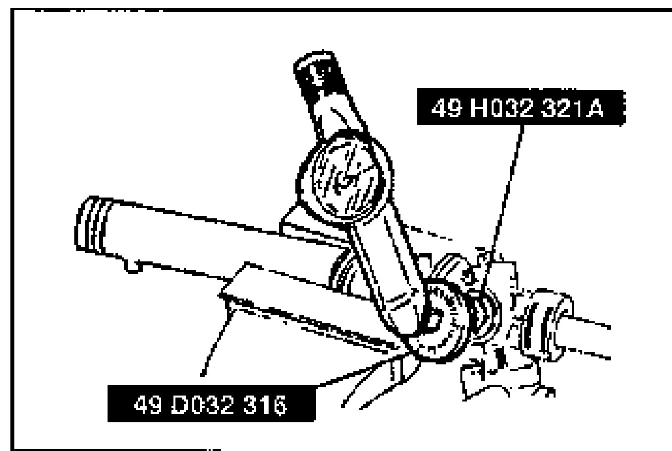
- 4(4) Tighten the adjusting cover to 9.8 N·m {100 kgf·cm, 87 in·lbf}, then loosen it.
- 5(5) Tighten again to 4.5—5.3 N·m {45—55 kgf·cm, 40—47 in·lbf}, and then return it 45°.
- 6(6) Measure pinion torque with the SST and a pull scale.
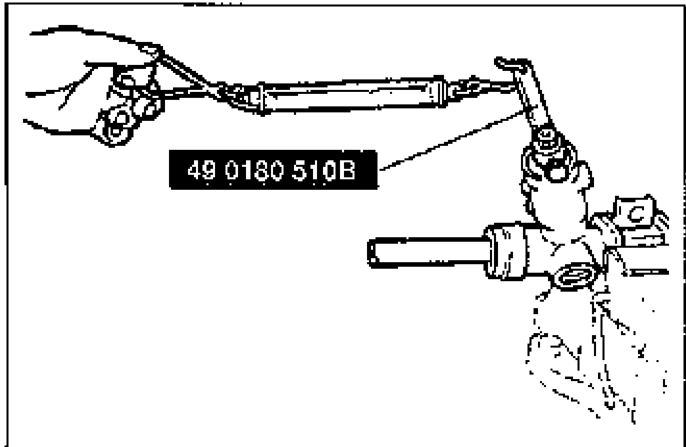
- 7(7) If not within specification, repeat steps (5) through (6).
- 8(8) Apply thread sealant to the threads of the locknut.
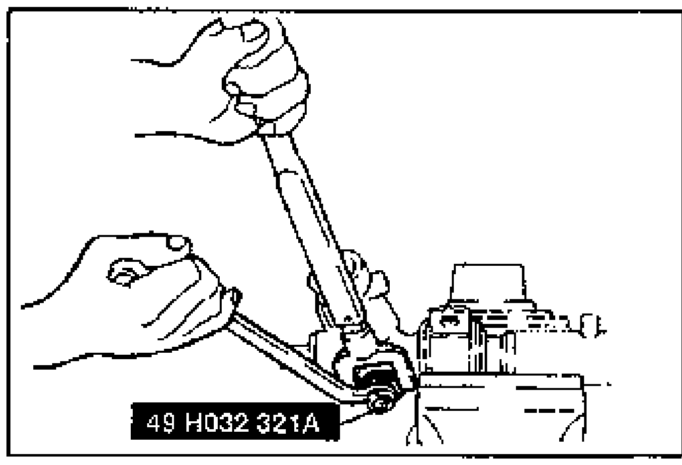
- 9(9) Use the SST to tighten the locknut.
| Specification | Value |
|---|---|
| Center of rack ±90°Pull scale reading: 1.0—1.2 kgf {2.2—2.6 lbf} | 1.0—1.3N·m {10—14 kgf·cm, 8.7—12.1 in·lbf} |
| At other positionPull scale reading: 1.7 kgf {3.7 lbf} max. | 1.6N·m {17 kgf·cm, 14.7 in·lbf} max. |
Center of rack ±90°Pull scale reading: 1.0—1.2 kgf {2.2—2.6 lbf}
1.0—1.3N·m {10—14 kgf·cm, 8.7—12.1 in·lbf}
At other positionPull scale reading: 1.7 kgf {3.7 lbf} max.
1.6N·m {17 kgf·cm, 14.7 in·lbf} max.
| Specification | Value |
|---|---|
| Tightening torque (adjusting cover locknut) | ≈490 - 569N·m |
Tightening torque (adjusting cover locknut)
490 - 569N·m
19. Tie rod
- 1(1) Secure the rack in a vise.
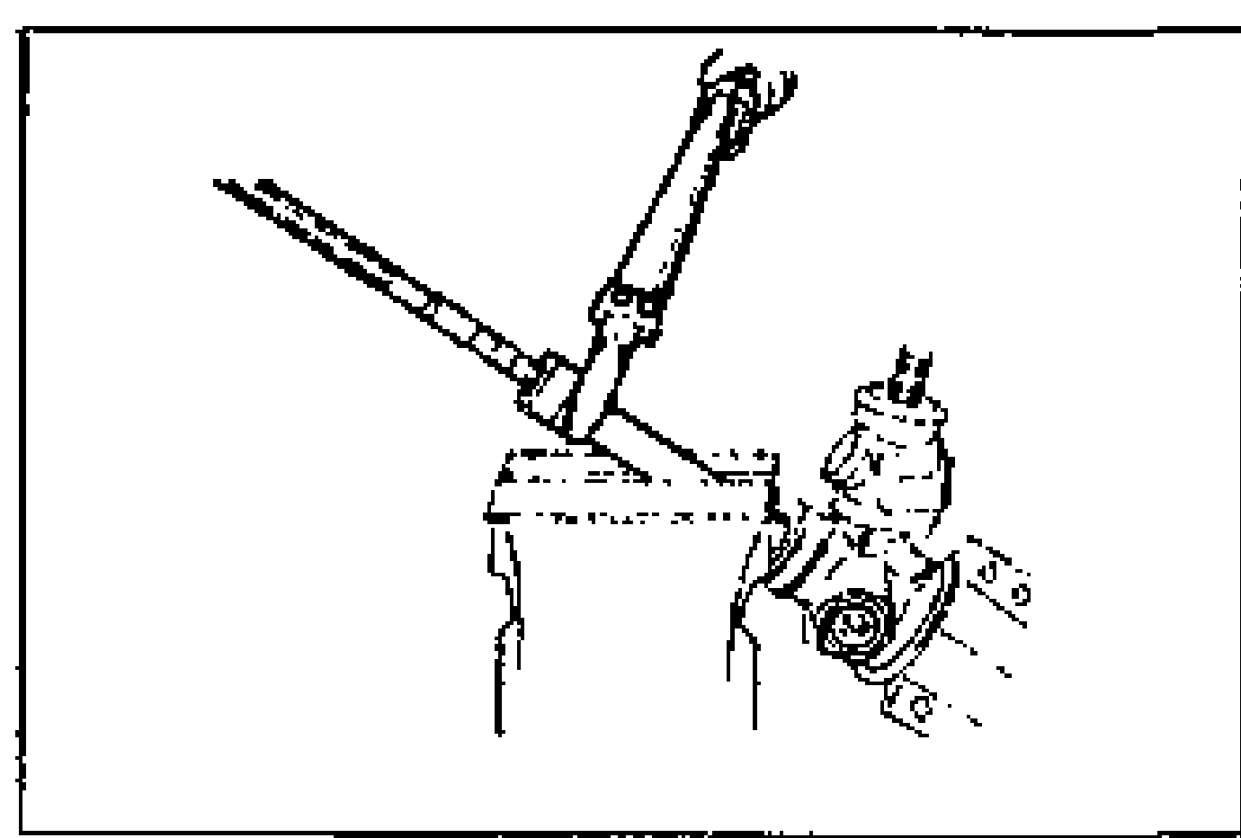
- 2(2) Install the tie rod onto the rack.
| Specification | Value |
|---|---|
| Tightening torque (tie rod) | ≈1206 - 1393N·m |
Tightening torque (tie rod)
1206 - 1393N·m