
ENGINE SPEED SENSING POWER STEERING — Steering Column Disassembly Note / Inspection
N-15prose procedureSteering shaft specified length differs between air-bag-equipped vehicles (570.6—572.6 mm) and non-air-bag Canada vehicles (558.3—560.3 mm).
Disassembly Note
Steering lock assembly
Use a chisel to make a groove in the head of the steering lock mounting bolts. Remove the bolts with a screwdriver; then remove the steering lock assembly.
Inspection
Check for the following and replace the assembly if necessary.
Steering shaft assembly
- 1Column bushing wear.
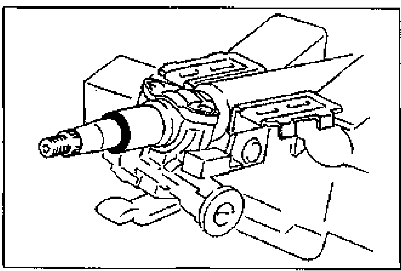
- 2Steering shaft length.
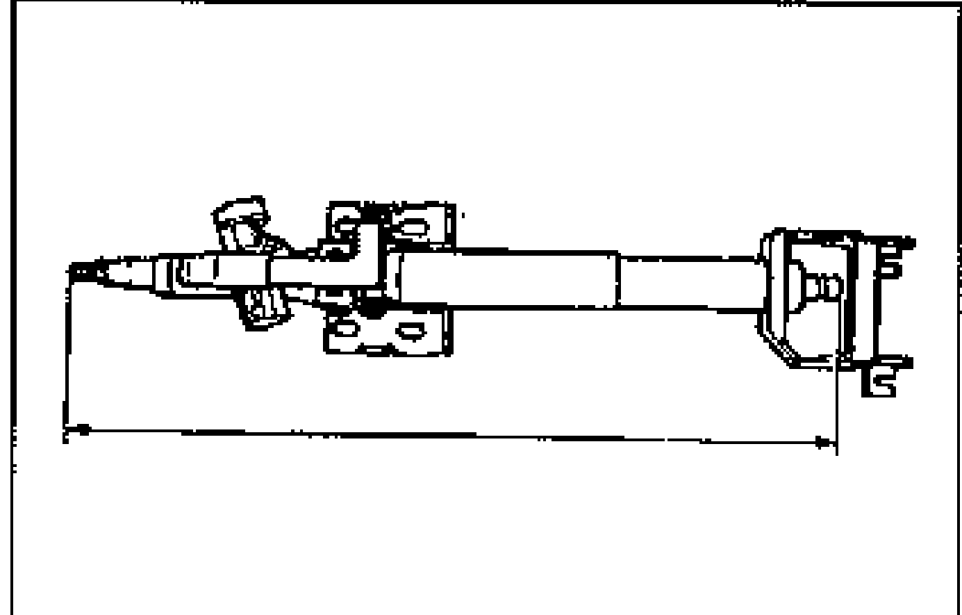
| Specification | Value |
|---|---|
| Specified length (With air bag)With air bag | 570.6—572.6mm {22.47—22.54 in} |
| Specified length (Without air bag, Canada)Without air bag (Canada) | 558.3—560.3mm {21.99—22.05 in} |
Specified length (With air bag)With air bag
570.6—572.6mm {22.47—22.54 in}
Specified length (Without air bag, Canada)Without air bag (Canada)
558.3—560.3mm {21.99—22.05 in}
Inspection of tilt operation
Check the following and repair or replace if necessary.
Inspection of tilt operation
- 1Adjust lever operates smoothly to locked position from unlocked position.
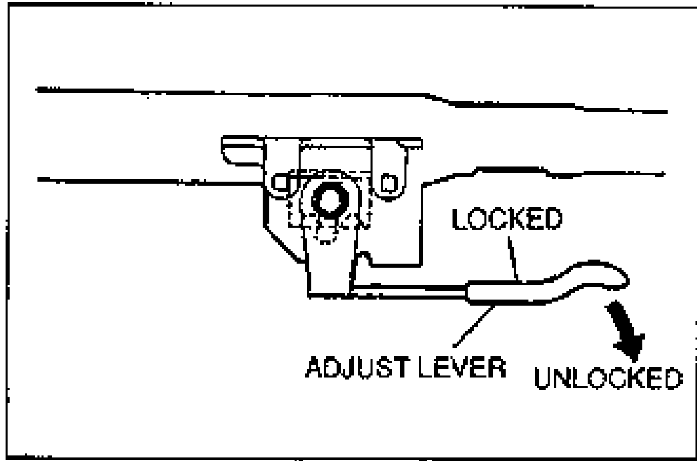
- 2Steering shaft is held securely in the locked position.
Intermediate shaft and universal joint
Universal joint and intermediate shaft looseness, abnormal noise, or sticking.