
WHEEL ALIGNMENT
R-7prose procedurePRE-INSPECTION
- 1Check the tire inflations and set to the recommended pressure, if necessary.
- 2Inspect the front wheel bearing play; replace the bearing if necessary.
- 3Inspect the wheel and tire runout.
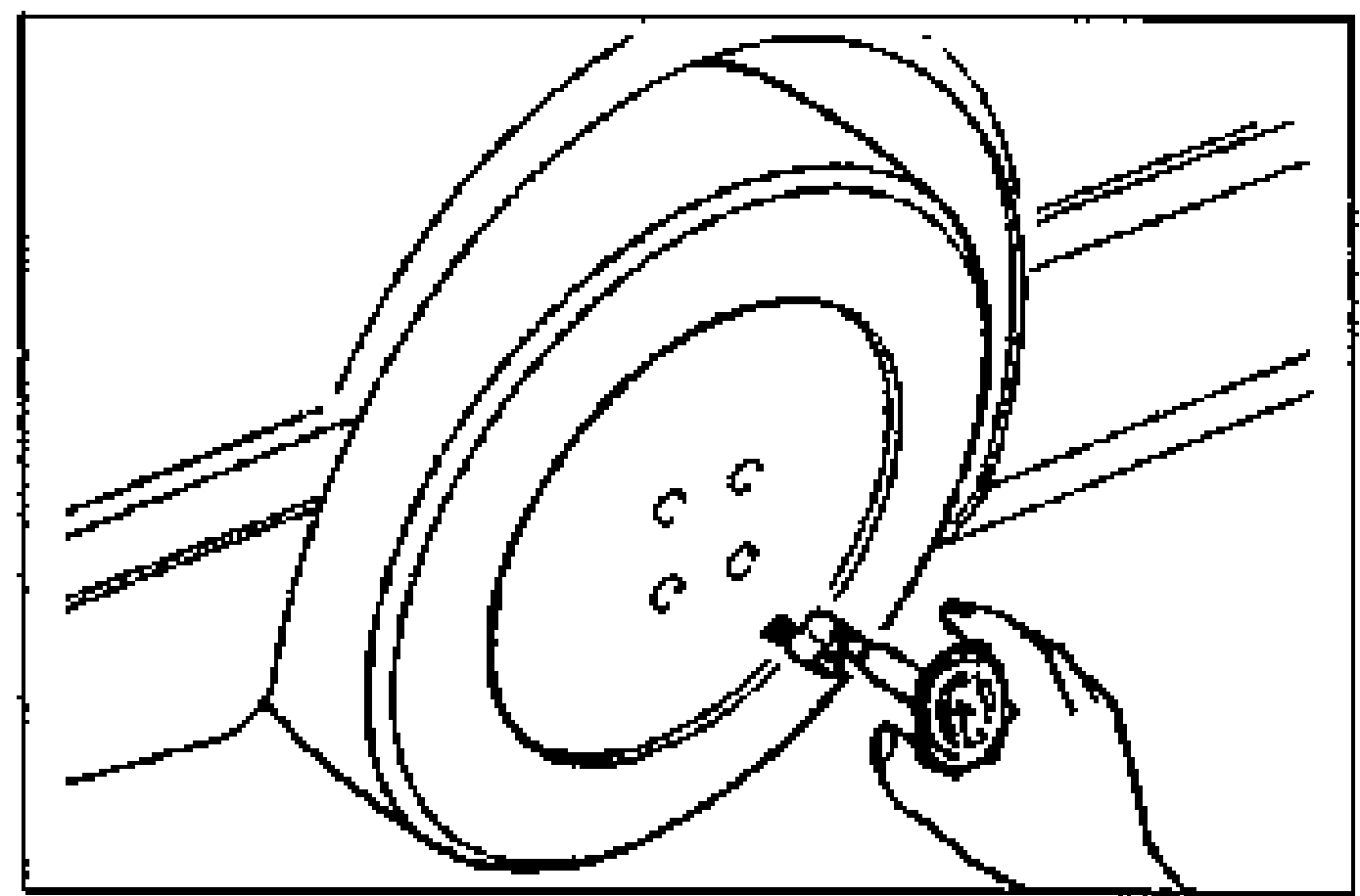
- 4Inspect the ball joints and steering linkage for any excessive looseness.
- 5The vehicle must be on level ground and have no luggage or passenger load.
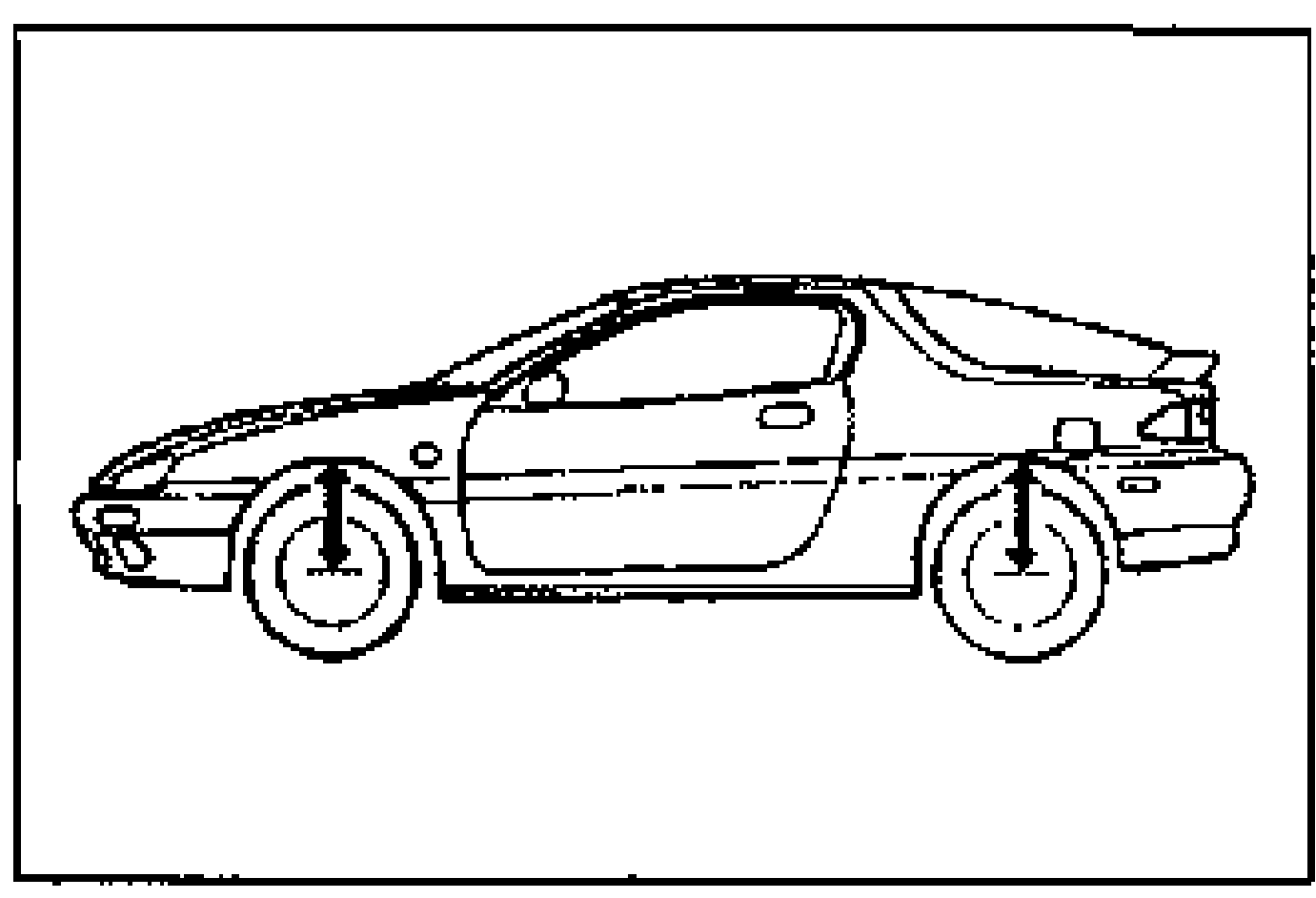
- 6The difference in height between the left and right sides from the center of the wheel to the fender brim must not exceed 10 mm {0.39 in}.
- 7Shake the vehicle to check operation of the shock absorbers.
FRONT WHEEL ALIGNMENT
Specifications (Unladen) *1
Front Wheel Alignment Specifications (Unladen) *1
Maximum steering angle
Inner
Specifications39°31' ± 2°
Maximum steering angle
Outer
Specifications32°54' ± 2°
Total toe-in
mm {in}
Specifications3 ± 4 {0.12 ± 0.15}
Total toe-in
Degree
Specifications0.3° ± 0.4° *2
Camber angle *3
Specifications-0°58' ± 1°
Caster angle *3
Specifications2°46' ± 1°
SAI *4
Specifications14°16'
NOTE
*1 • Fuel tank full: radiator coolant and engine oil at specified level, and spare tire, jack and tools in designated position
• Adjust to the median when carrying out wheel alignment
*2 Indicates measurements made by using the 4-wheel alignment tester
*3 Difference between left and right must not exceed 1.5°
*4 SAI: Steering Axis Inclination
Adjustment
Maximum steering angle
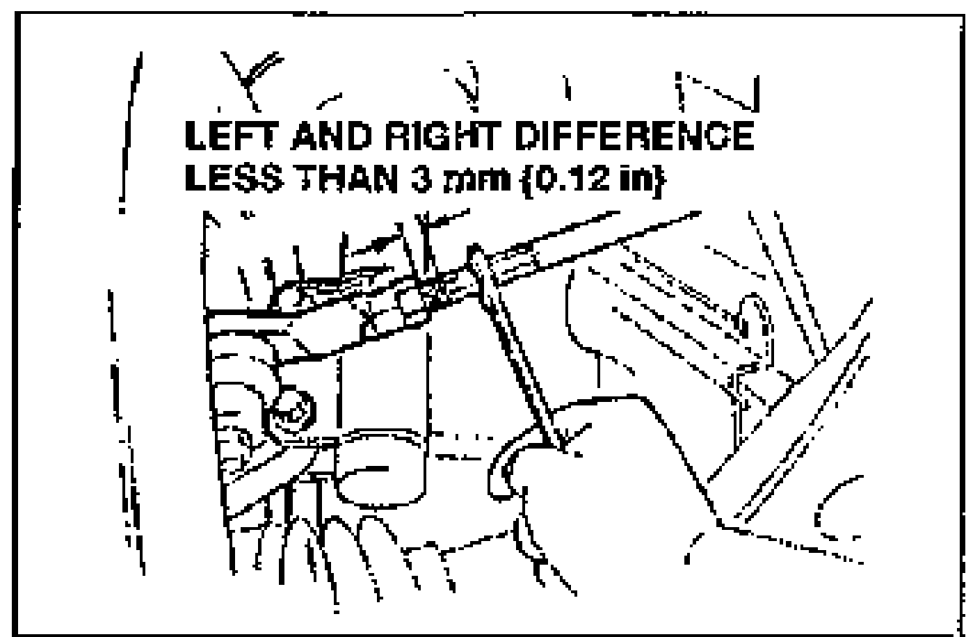
- 1Loosen the left and right tie rod locknuts, then turn the tie rods equally.
| Specification | Value |
|---|---|
| Maximum left/right difference | 3 mm {0.12 in} |
Maximum left/right difference
3 mm {0.12 in}