
FRONT SUSPENSION (STRUT) — FRONT CROSSMEMBER Removal / Inspection / Installation
R-26parts diagramLower inset diagrams labeled B6DOHC indicate B6 (1.6L I4) engine-specific steering-gear and exhaust-pipe details; main exploded view appears shared. Numbered parts legend is on the following page (R-27).
FRONT CROSSMEMBER
Removal / Inspection / Installation
- 1Jack up the front of the vehicle and support it with safety stands.
- 2Remove the wheels.
- 3Remove the undercover.
- 4Remove in the order shown in the figure, referring to Removal Note.
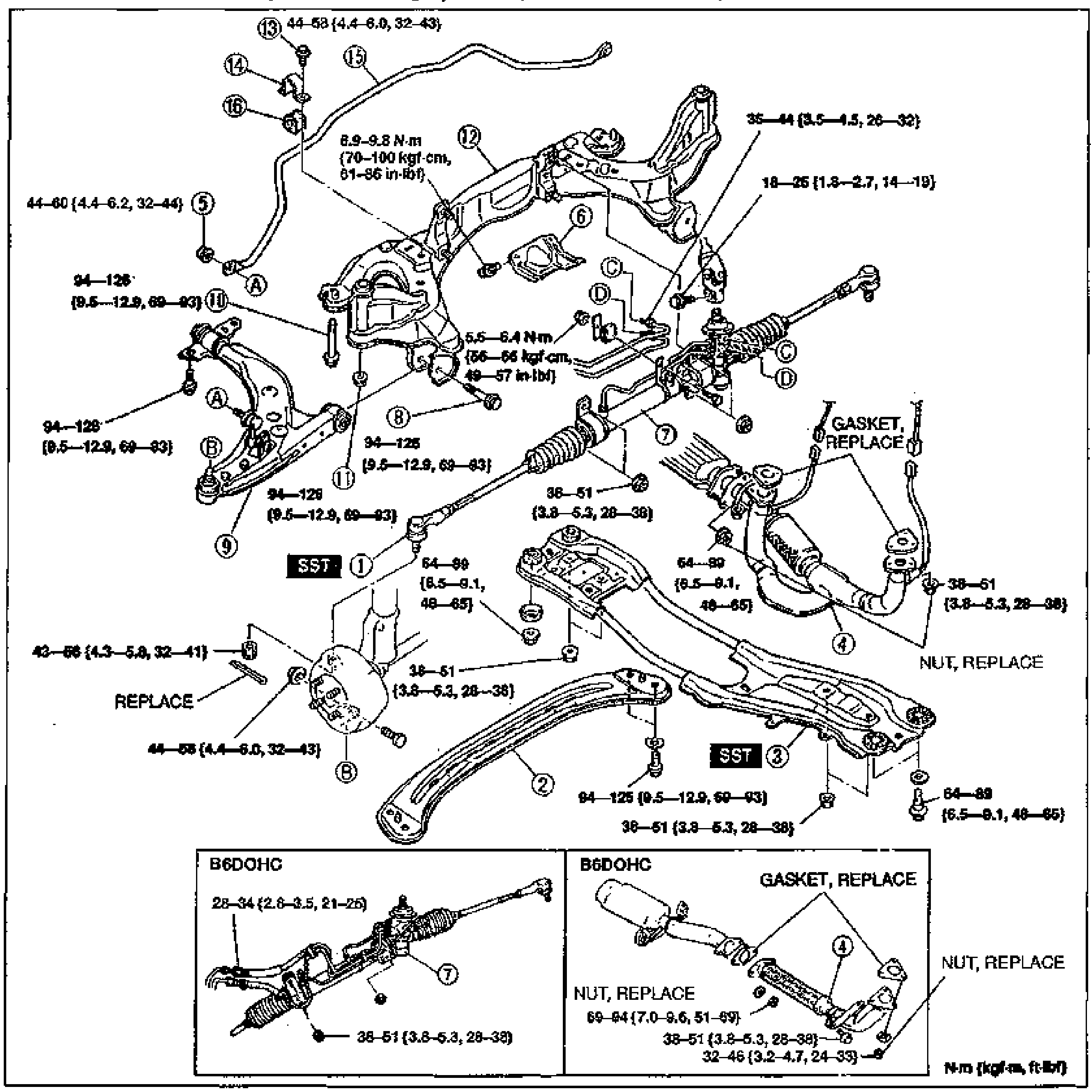
- 5Visually inspect each part and replace as necessary.
- 6Install in the reverse order of removal.
- 7Loosely tighten the lower arm bolts and the stabilizer bracket bolts. Tighten all other nuts and bolts to the specified torques.
- 8Install the wheels. (Tightening torque: 89-117 N·m {9.0-12.0 kgf·m, 66-86 ft·lbf})
- 9Lower the vehicle.
- 10With the vehicle unloaded, tighten the lower arm bolts and the stabilizer bracket bolts to the specified torque.
- 11Adjust the front wheel alignment. (Refer to page R-7.)
- 12Bleed the air from the power steering system. (Refer to section N.)
NOTE
Lower inset detail views are labeled B6DOHC, showing the steering gear and linkage (item 7) with 28-34 {2.8-3.5, 21-25} and 38-51 {3.8-5.3, 28-38} torques, and the front exhaust pipe (item 4) with GASKET/NUT REPLACE notes and torques 69-94 {7.0-9.6, 51-69}, 38-51 {3.8-5.3, 28-38}, 32-46 {3.2-4.7, 24-33}. Parts-name legend continues on page R-27.