
DRIVE SHAFT
M-31prose procedureSeparate SST and dimensions for B6 DOHC vs K8 DOHC; B6 DOHC MTX (manual transaxle) right-side length given.
ABS sensor rotor
NOTE
The ABS sensor rotor does not need to be removed unless you are replacing it.
Tap the sensor rotor off the drive shaft with a chisel.
Assembly Note
ABS sensor rotor
Set a new ABS sensor rotor on the drive shaft in the direction as shown, and press it onto the shaft assembly by using the SST.
Dynamic damper / Band
- 1Push the joint fully toward the drive shaft.
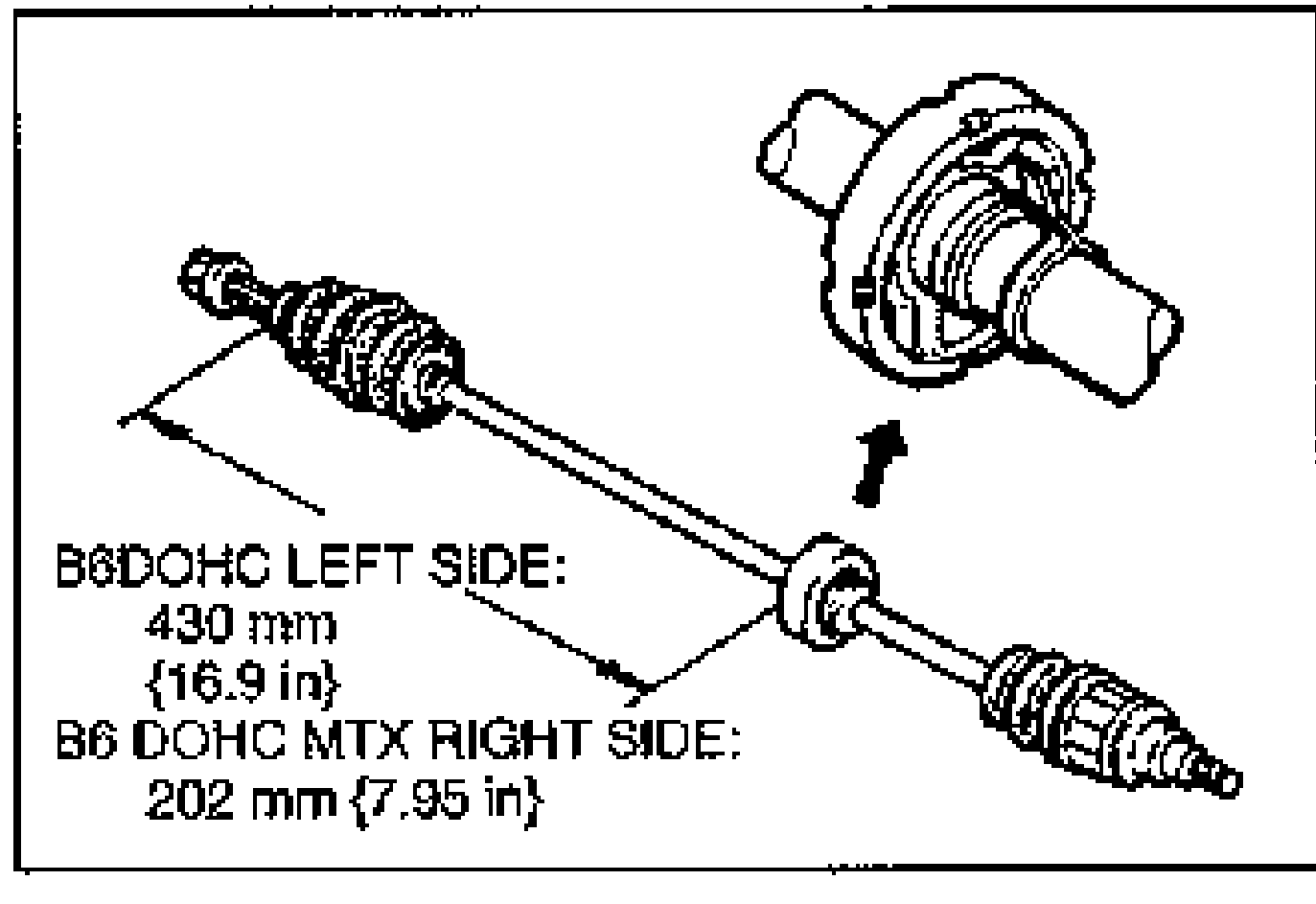
- 2Make sure the dynamic damper position is as shown in the figure.
- 3Install the band and dynamic damper.
- 4Fold the band back by pulling on the end of it with pliers, so that the end of the band is pointing opposite the forward revolving direction of the shaft.
- 5Lock the end of the band by bending the locking clip.
Boot
NOTE
The initials TJ and BJ are stamped on the wheel-side and differential-side boots respectively.
Boot
- 1Wrap the splines of the transaxle side shaft, and install the boot, noting the shape and size of each one in the figure.
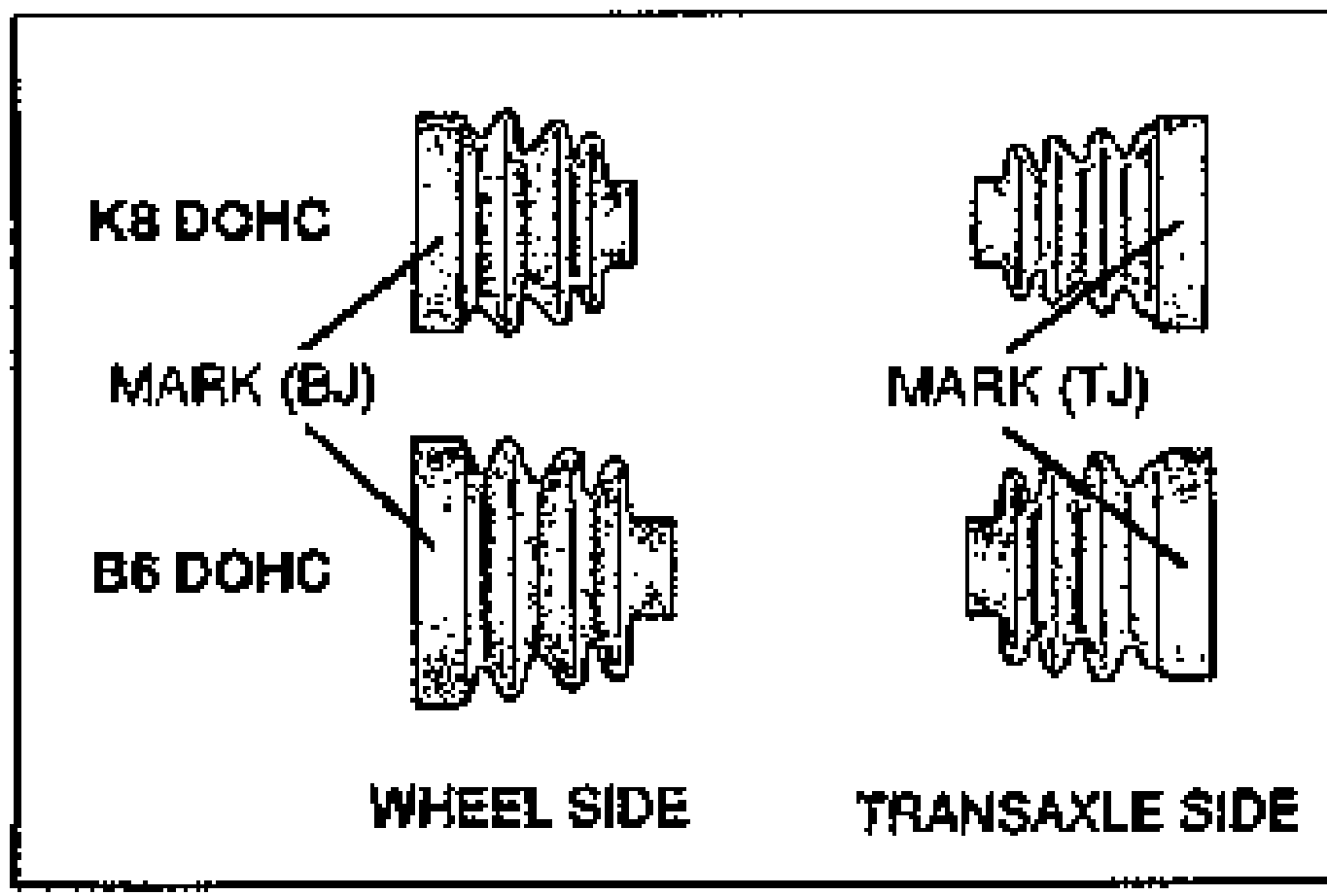
- 2Fill the wheel side boot with the grease, supplied in the boot and joint kit.
| Specification | Value |
|---|---|
| Grease amountB6 DOHC | 60–80 g {2.12–2.82 oz} |
| Grease amountK8 DOHC | 80–100 g {2.83–3.53 oz} |
Grease amountB6 DOHC
60–80 g {2.12–2.82 oz}
Grease amountK8 DOHC
80–100 g {2.83–3.53 oz}
Tripod joint / Snap ring
CAUTION
Do not damage the bearing.
Tripod joint / Snap ring
- 1Align the marks and install the tripod joint with a bar and a hammer.
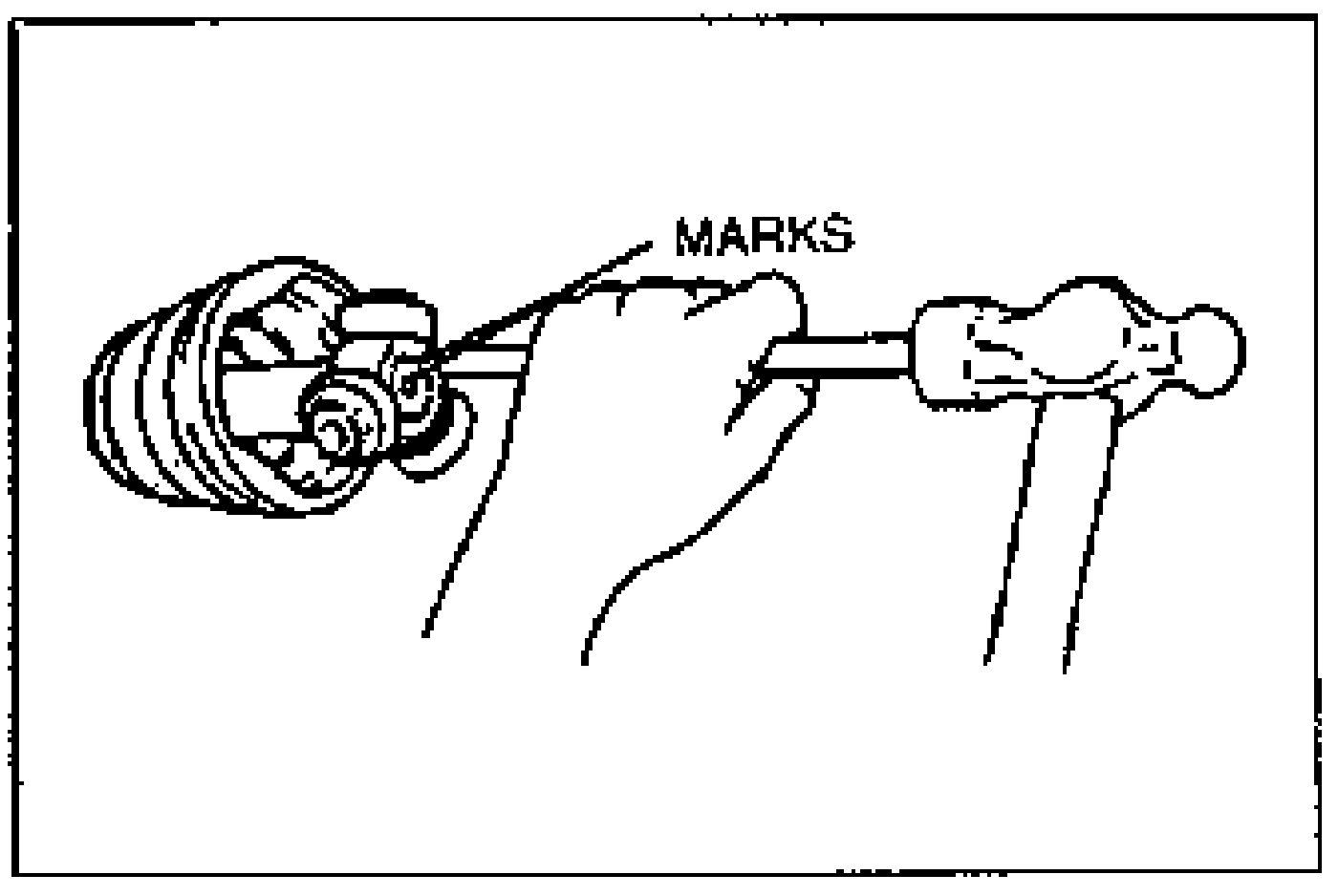
- 2Install the new snap ring with snap-ring pliers.