
Measuring continuity/resistance
Z-GI-15prose procedureChecking switches
Touch the ohmmeter probes to the switch terminals to check continuity.
CAUTION
Verify the operating state of the switch before checking continuity because readings vary accordingly.
Checking diodes
Continuity is checked according to the direction of the positive (+) and negative (-) probes of the ohmmeter in the circuit containing the diode.
NOTE
The negative (-) probe of the ohmmeter is connected to the positive terminal of the internal ohmmeter battery, the positive (+) probe to the negative terminal of the battery.
Diode continuity check
Ohmmeter connected across diode in forward direction
ContinuityYes
Ohmmeter connected across diode in reverse direction
ContinuityNo
Checking sensors and solenoid valves
Connect the ohmmeter probes to the sensor or solenoid valve terminals to check resistance.
CAUTION
Verify the operating state of the sensor before checking resistance because readings vary accordingly.
Checking condensers
- 1Short between the terminals with a jumper wire to discharge the capacitor.
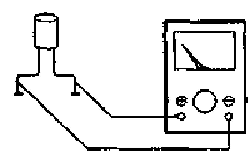
- 2Set the ohmmeter range to x 10kΩ and connect it to the capacitor terminals.
- 3The capacitor is good if the needle of the ohmmeter swings once and returns to its original position.