
K8 DOHC - Engine Control System harness routing / connector locations
Z-41component photoK8 DOHC V6. Connector/harness location diagram. Codes B2-C8 read as printed (likely the LH oxygen sensor companion to B2-08).
B-2a
NOTE
Harness color: FRONT (solid) / ENGINE.
Component LocationFig. fig1
K8 DOHC engine control system harness routing and connector locations on the vehicle.
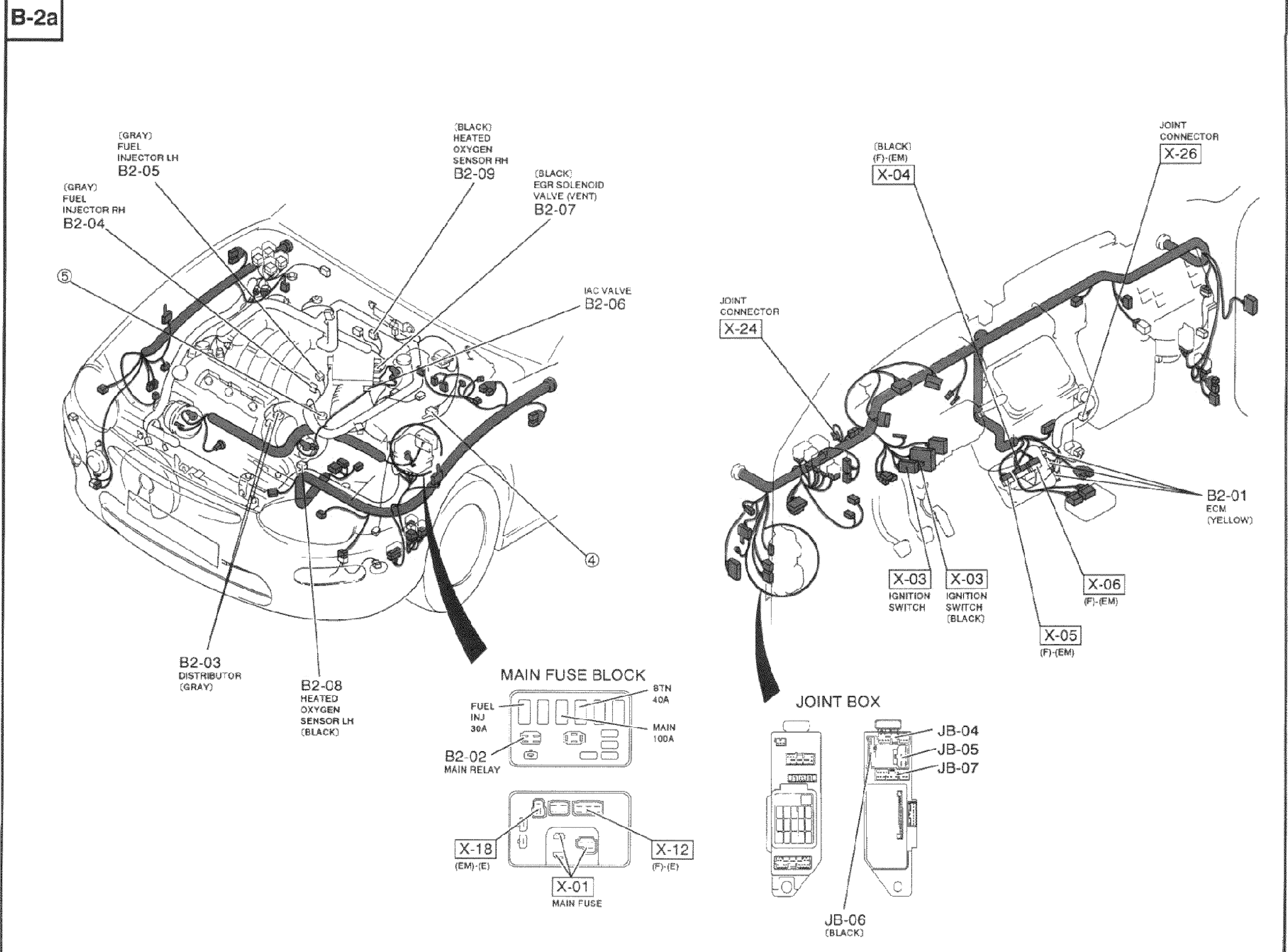
B-2a
1B2-04(Fuel Injector RH (Gray))
2B2-05(Fuel Injector LH (Gray))
3B2-09(Heated Oxygen Sensor RH (Black))
4B2-07(EGR Solenoid Valve (Vent) (Black))
5B2-06(IAC valve)
6B2-03(Distributor (Gray))
7B2-C8(Heated Oxygen Sensor LH (Black))
8B2-02(Main Relay)
9B2-01(ECM (Yellow))
10X-24(Joint connector)
11X-26(Joint connector)
12X-04(Joint connector (Black))
13X-03(Ignition switch (Black))
14X-05((F)-(EM))
15X-06((F)-(EM))
16X-01(Main Fuse)
17X-18((EM)-(E))
18X-12((F)-(E))
19JB-04(Joint Box)
20JB-05(Joint Box)
21JB-06(Joint Box (Black))
22JB-07(Joint Box)