
Measuring voltage
Z-GI-14prose procedureChecks
- 1Connect a voltmeter or test lamp to the measuring points.
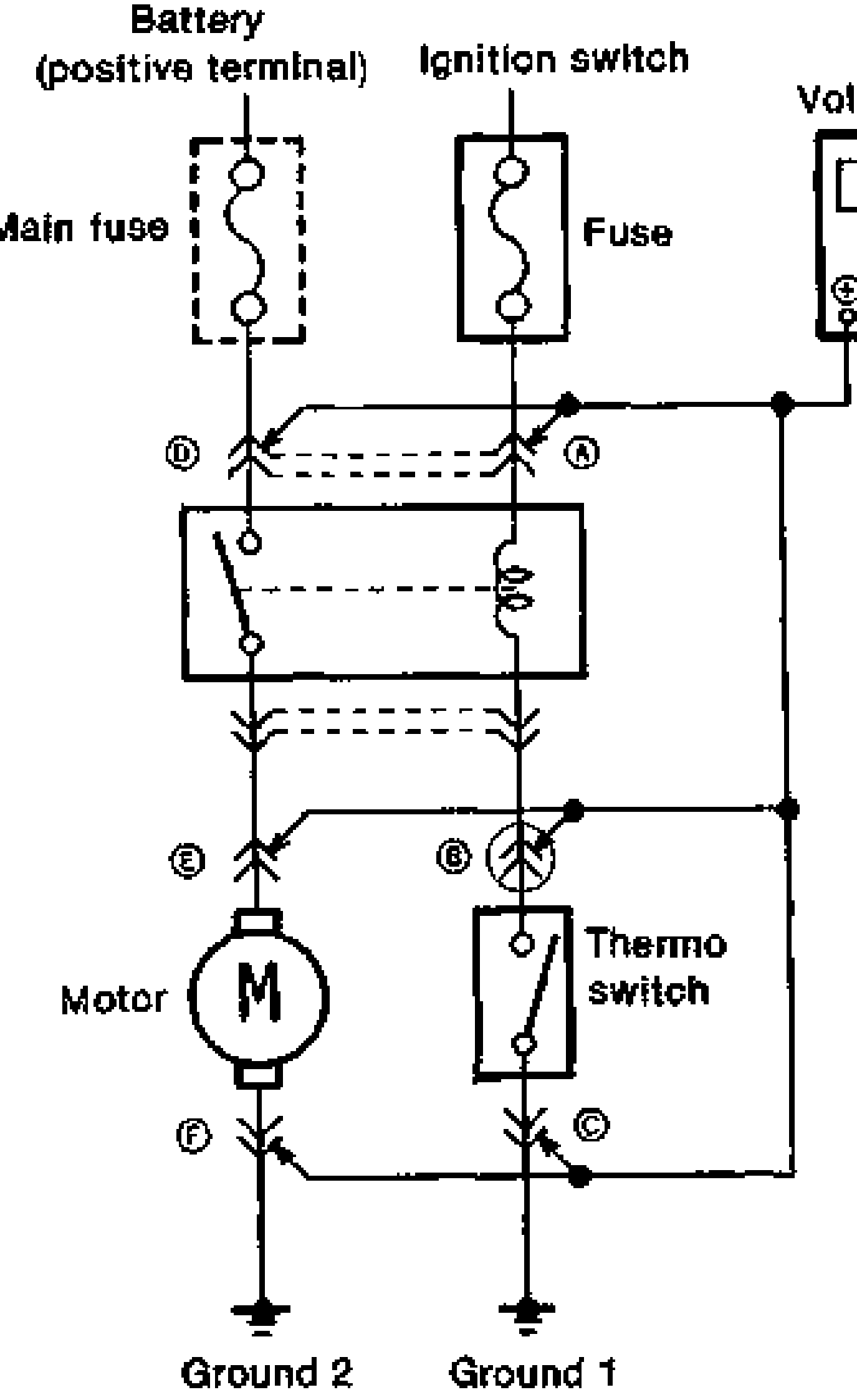
Circuit operation (normal)
A
Ignition switch: OFF0V x
Ignition switch: ON / Thermo switch: OFF12V O
Ignition switch: ON / Thermo switch: ON12V O
B
Ignition switch: OFF0V x
Ignition switch: ON / Thermo switch: OFF12V O
Ignition switch: ON / Thermo switch: ON0V x
C
Ignition switch: OFF0V x
Ignition switch: ON / Thermo switch: OFF0V x
Ignition switch: ON / Thermo switch: ON0V x
D
Ignition switch: OFF12V O
Ignition switch: ON / Thermo switch: OFF12V O
Ignition switch: ON / Thermo switch: ON12V O
E
Ignition switch: OFF0V x
Ignition switch: ON / Thermo switch: OFF0V x
Ignition switch: ON / Thermo switch: ON12V O
F
Ignition switch: OFF0V x
Ignition switch: ON / Thermo switch: OFF0V x
Ignition switch: ON / Thermo switch: ON0V x
NOTE
O : Test lamp ON x : Test lamp OFF
Precautions during checks
CAUTION
A voltmeter probe may momentarily connect a terminal when inserted into the connector and give an erroneous reading when checking for improperly engaged connectors, poor terminal contacts, or loose terminals.
NOTE
Touch the voltmeter probe to the ground wire when checking the ground circuit.