
Turn and Hazard Warning Lights — Harness Routing / Connector Locations (Circuit F-1)
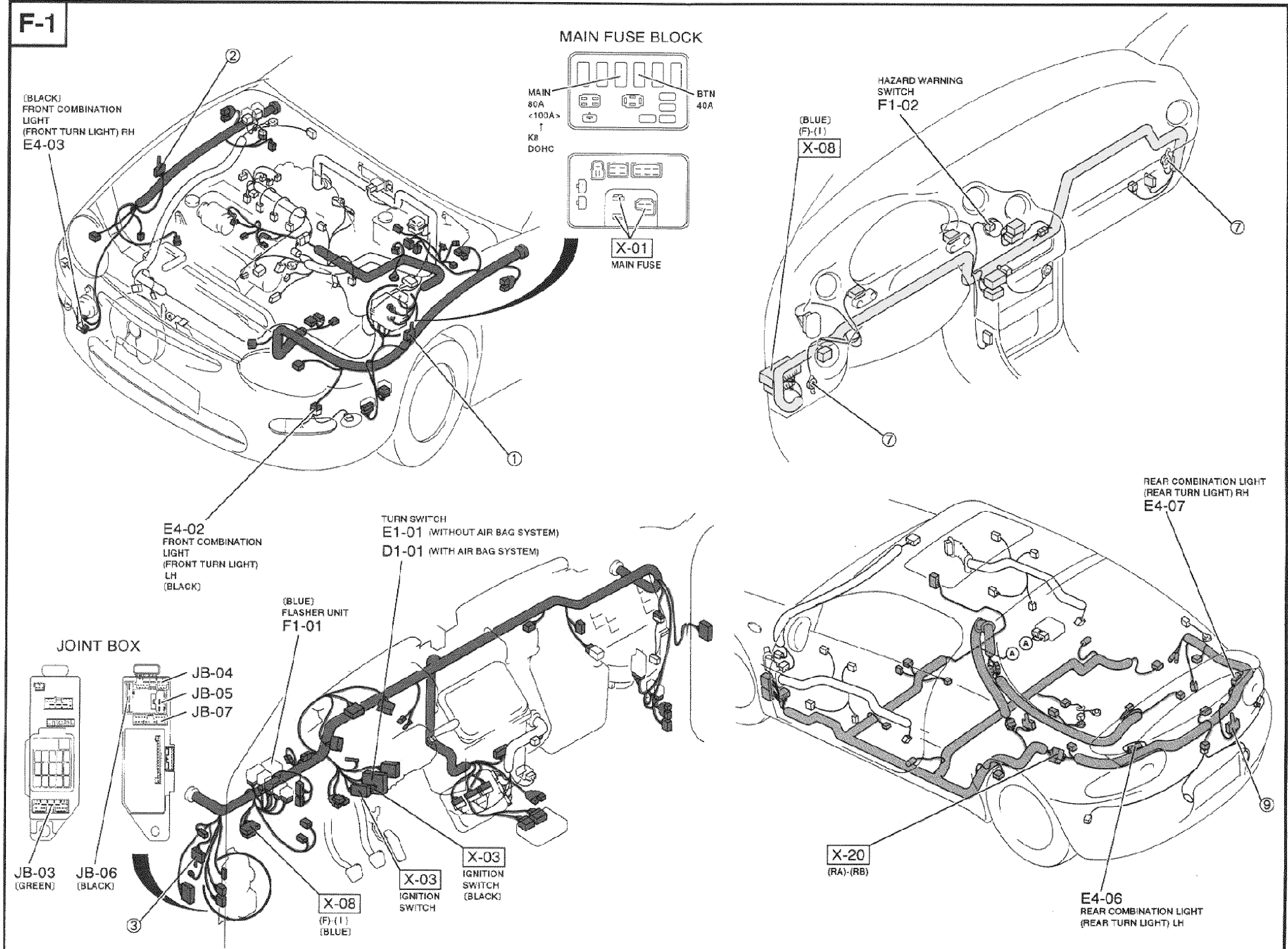
Z-75wiring diagramE1-01 turn switch without air bag system; D1-01 turn switch with air bag system.
Turn and Hazard Warning Lights — Harness Routing (F-1)
NOTE
Harness color legend: FRONT, ENGINE, INSTRUMENT-PANEL. This page shows the physical routing and connector locations for the F-1 circuit; refer to page Z-74 for the schematic.
Component LocationFig. fig1
Connector and component locations for the Turn and Hazard Warning Lights circuit overlaid on the vehicle body.
F-1
1E4-02(Front LH — Front Combination Light (front turn light), black)
2E4-03(Front RH — Front Combination Light (front turn light), black)
3X-01(Main Fuse Block — Main Fuse)
4JB-03 / JB-04 / JB-05 / JB-06 / JB-07(Joint Box (lower left))
5F1-01(Flasher Unit (blue))
6E1-01(Turn Switch (without air bag system))
7D1-01(Turn Switch (with air bag system))
8X-03(Ignition Switch (black))
9F1-02(Hazard Warning Switch (dashboard))
10X-06(Dashboard area connector)
11X-20(Rear harness connector)
12E4-06(Rear LH — Rear Combination Light (rear turn light))
13E4-07(Rear RH — Rear Combination Light (rear turn light))