
Condenser Fan System (B6 DOHC) — Harness Routing / Connector Locations (Circuit G-1)
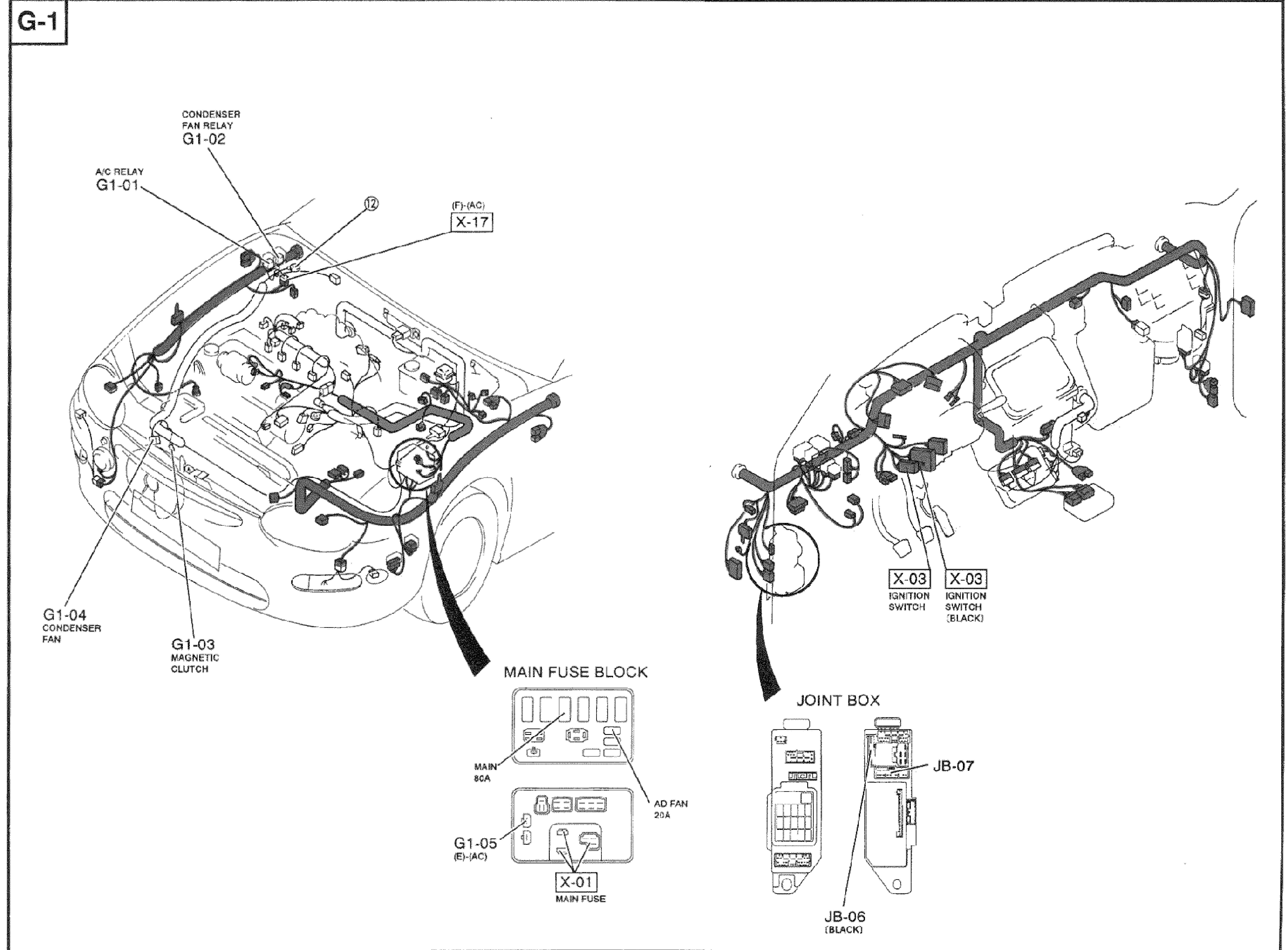
Z-81wiring diagramB6 DOHC condenser fan system harness routing.
Condenser Fan System (B6 DOHC) — Harness Routing (G-1)
NOTE
Harness color legend: FRONT, ENGINE. This page shows the physical routing and connector locations for the G-1 circuit; refer to page Z-79 for the schematic.
Component LocationFig. fig1
Connector and component locations for the B6 DOHC condenser fan system overlaid on the vehicle body.
G-1
1G1-01(Engine compartment — A/C Relay)
2G1-02(Engine compartment — Condenser Fan Relay)
3X-17((F)(AC) connector)
4G1-04(Condenser Fan (front))
5G1-03(Magnetic Clutch (front))
6X-01(Main Fuse Block — Main Fuse (MAIN 80A, AD FAN 20A))
7G1-05((E)(AC) connector between engine and A/C harness)
8X-03(Ignition Switch (one standard, one black))
9JB-06 / JB-07(Joint Box (lower right); JB-06 black)