Mazda MX-3 silhouetteMX-3

Air Bag System harness routing / component location

Z-123wiring diagram

MAIN FUSE BLOCK shows MAIN 80A <100A> for K8 DOHC. Connector colors noted: ORANGE/BLUE and BLUE air bag connectors, BLACK ignition switch / JB-06.

Component LocationFig. fig1

Air bag system component locations and harness routing on the vehicle.
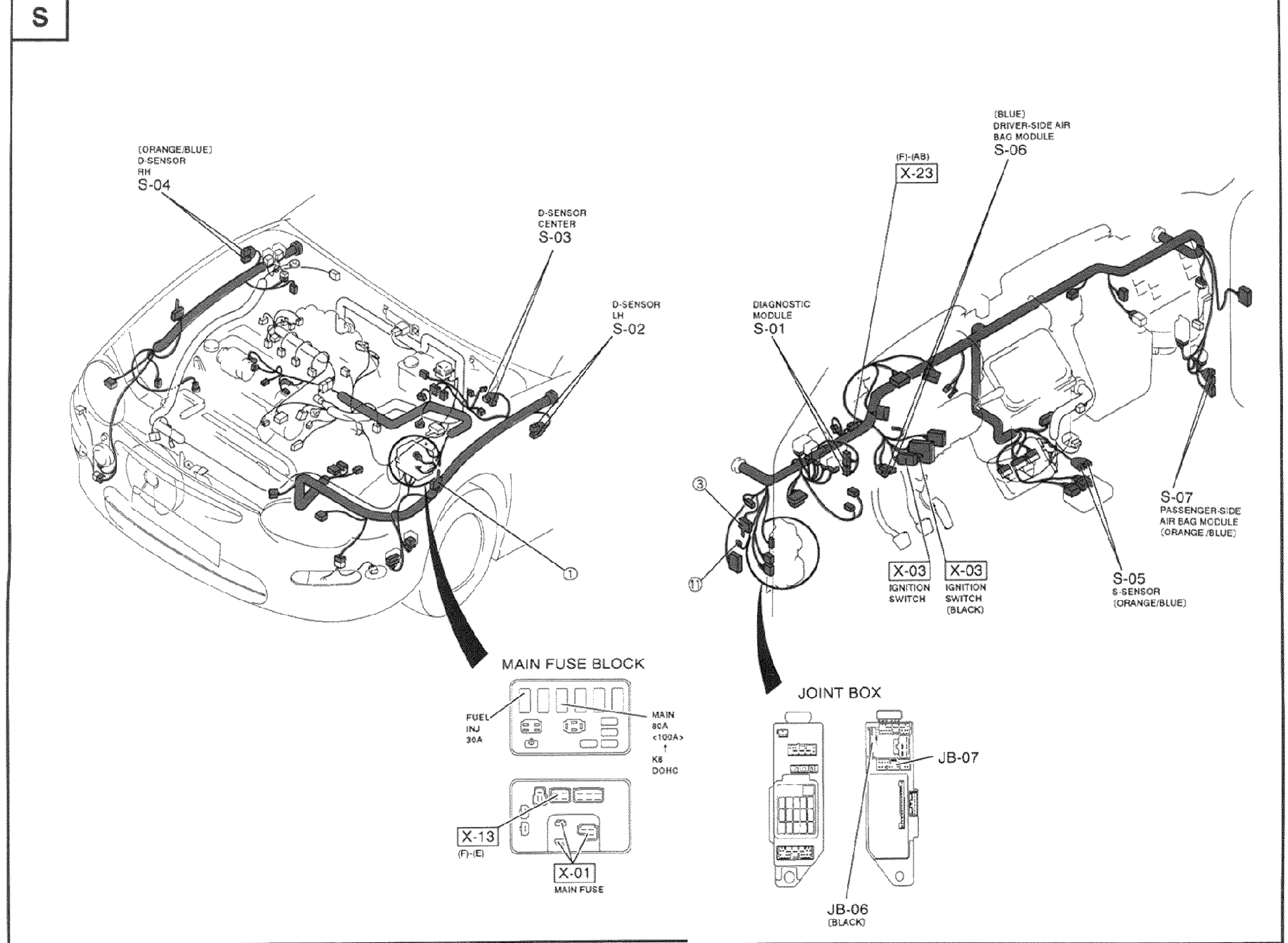
Vehicle wiring-harness routing illustration for the air bag system. Left half shows the engine bay / front of car with the front wiring harness; right half shows the cabin / instrument panel harness. Harness color legend at top: HARNESS COLOR — FRONT (shaded), ENGINE (shaded). Component callouts: D-SENSOR RH S-04 (ORANGE/BLUE), D-SENSOR CENTER S-03, D-SENSOR LH S-02, DIAGNOSTIC MODULE S-01, DRIVER-SIDE AIR BAG MODULE S-06 (BLUE), PASSENGER-SIDE AIR BAG MODULE S-07 (ORANGE/BLUE), G-SENSOR S-05 (ORANGE/BLUE), connector X-23 (F)-(AB), IGNITION SWITCH X-03 and X-03 (BLACK). Sub-diagrams at bottom: MAIN FUSE BLOCK (FUEL INJ 30A; MAIN 80A <100A> K8 DOHC; X-13 (F)-(I); X-01 MAIN FUSE) and JOINT BOX (JB-07; JB-06 BLACK).
1S-04(D-sensor RH (ORANGE/BLUE))
2S-03(D-sensor center)
3S-02(D-sensor LH)
4S-01(Diagnostic module)
5S-06(Driver-side air bag module (BLUE))
6S-07(Passenger-side air bag module (ORANGE/BLUE))
7S-05(G-sensor (ORANGE/BLUE))
8X-23(Connector (F)-(AB))
9X-03(Ignition switch)
10X-03(Ignition switch (BLACK))
11X-13(Main fuse block connector (F)-(I))
12X-01(Main fuse)
13JB-07(Joint box)
14JB-06(Joint box (BLACK))

Search Manual

Search pages, specs, and procedures