
Connector Locations (Audio)
J-6component photoComponent LocationFig. fig1
Physical mounting locations of audio-system connectors and components across four vehicle/harness views.
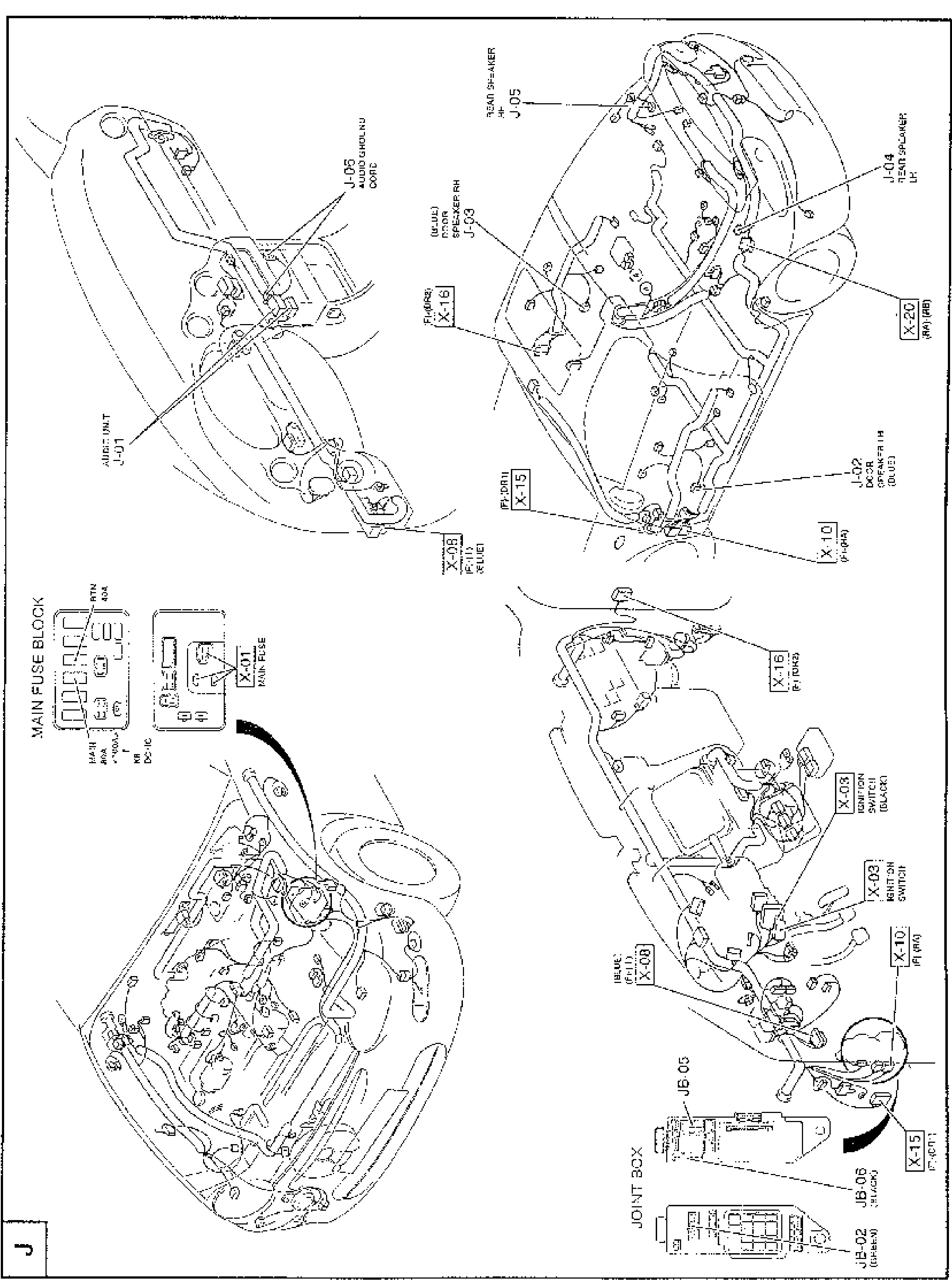
1J-01(Audio unit connector)
2J-05(Audio ground cord)
3X-01(Main fuse (main fuse block: MAIN 80A, BTN 40A, RTN 40A))
4J-04(Rear speaker LH connector)
5J-05(Rear speaker RH connector)
6J-03(Door speaker RH connector (blue))
7J-02(Door speaker LH connector (blue))
8X-03(Ignition switch connector (black))
9JB-05(Joint box)
10JB-06(Joint box (black))
11JB-02(Joint box (green))
12X-08(Inline connector (F-1)(blue))
13X-10(Inline connector (F)(RA))
14X-15(Inline connector (F)(DR1))
15X-16(Inline connector (F)(DR2))
16X-20(Inline connector (RA)(RB))