
COOLANT FAN SYSTEM
E2-11wiring diagramCircuit shows MTX (manual transaxle) coolant fan relay group; condenser fan group is for A/C-equipped vehicles.
SYSTEM CIRCUIT
Coolant Fan System Circuit
Components (16)
ECM (Water Temperature / Engine Condition)Engine coolant temperature sensorA/C switchClosed throttle positionIgnition switchData link connectorCoolant fan relay No.1Coolant fan relay No.2Coolant fan motorFan relay high No.1Fan relay high No.2Fan relay lowA/C relayCondenser fan motorMagnetic clutchBattery
Connections (6)
Engine coolant temperature sensor
Engine coolant temperature sensorECM (Water Temperature / Engine Condition)??
ECM (Water Temperature / Engine Condition)
ECM (Water Temperature / Engine Condition):LCoolant fan relay No.1??— LOW
ECM (Water Temperature / Engine Condition):3NFan relay high No.1??— MEDIUM/HIGH
ECM (Water Temperature / Engine Condition):2PFan relay high No.2??— HIGH
ECM (Water Temperature / Engine Condition):3LA/C relay??
Battery
BatteryCoolant fan relay No.1??
System Inspection
- 1Turn the ignition switch to OFF.
- 2Ground the TEN terminal of the data link connector and open the throttle slightly.
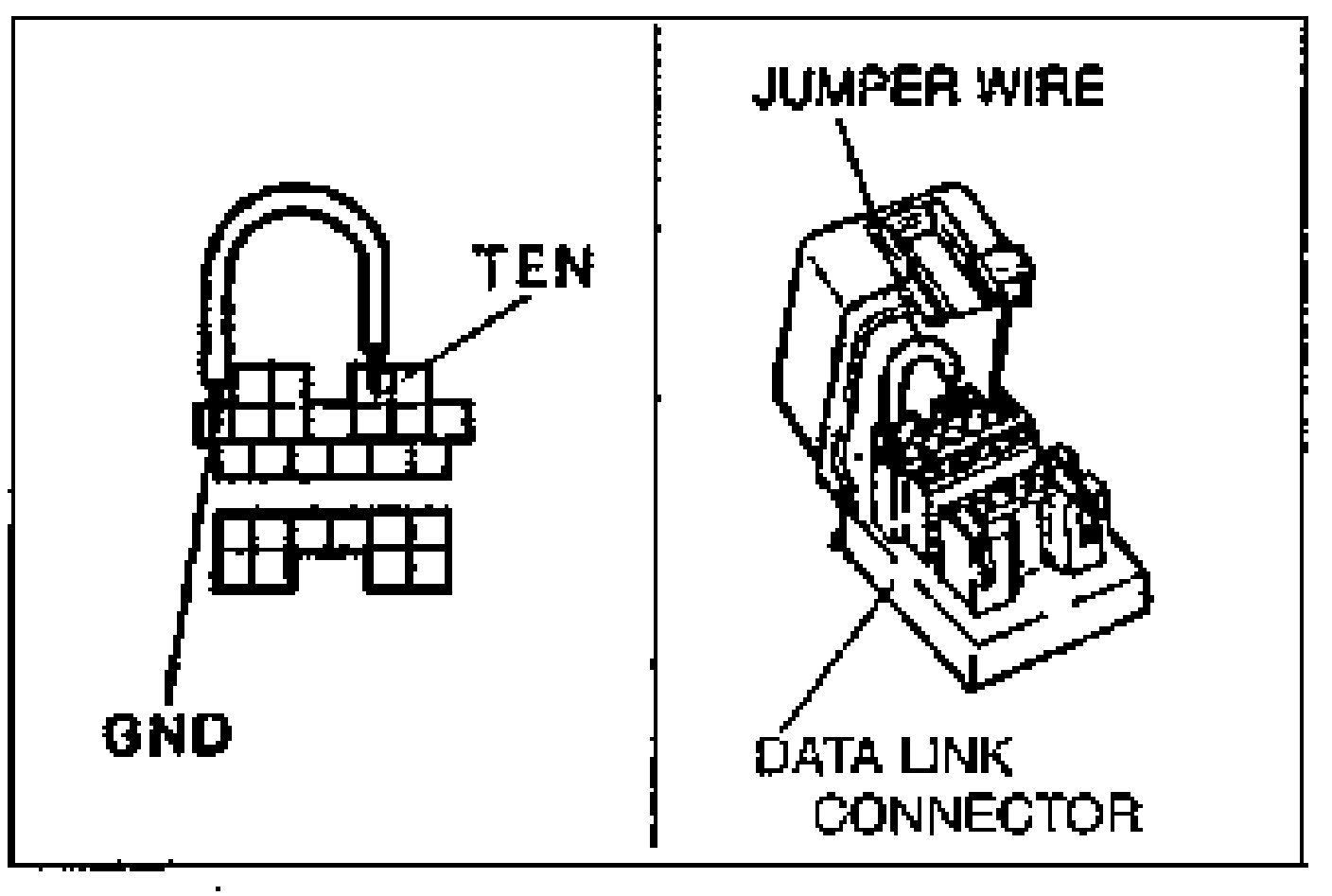
- 3Turn the ignition switch on and verify that the fan operates.
- 4If the fan does not operate, inspect the coolant fan system components and wire harness.
- 5Remove the filler cap and place a thermometer in the filler neck.
- 6Start the engine.
- 7Verify that the fan operates when the coolant temperature reaches approx. 100°C {212°F}.
- 8If it does, check the engine coolant temperature sensor. (Refer to page E2-14.)